Routers – Grass Valley NV9000-SE v.3.0 User Manual
Page 88
68
Rev 3.0 • 25 Mar 10
7. Routers
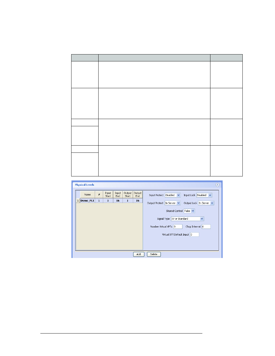
Adding a Router
Click
Add
to add a level, as shown in Figure 7-5. Click in the row under each column heading to
activate that field and enter information as follows:
Figure 7-5. Physical Level Section - Router Details Page
7 Repeat Step 6 until all physical levels in the router have been entered. To remove a row, select
the row and then click
Delete
.
Field
Description
Values
Name
Enter a descriptive name for the router. Up to 24 alphanumeric
characters may be entered. Do not use punctuation marks or
symbols.
This name is not seen by the operators; only by the NV9000-SE
user.
Alphanumeric
#
Numeric value identifying a particular physical level (partition) in
the router.
Enter a number for the router signal type for each physical level. If
multiple signal types are managed by the router, enter additional,
unique numbers, one for each signal type, creating a new row for
each signal. Each signal type is a separate, unique physical level.
0 through 250
Input Start
The logical number this physical level (partition) starts and ends
with for inputs.
Important: These numbers must match the number entered as the
‘Controller Input’ ‘start’ and ‘end’ in UniConfig when configuring
the router. For more information, see the UniConfig User’s Guide.
Typically 0 or 1
Input End
Output Start
The logical number this physical level starts and ends with for
outputs.
Important: These numbers must match the numbers entered as the
‘Controller Output’ ‘start’ and ‘end’ in UniConfig when
configuring the router. For more information, see the UniConfig
User’s Guide.
Typically 0 or 1
Output End