Analyzing reference machining, 7 load monit o ri ng – HEIDENHAIN CNC Pilot 4290 V7.1 User Manual
Page 104
104
3.7 Load Monit
o
ri
ng
Editing the load parameters
The “Display and adjust load parameters” dialog box displays the
parameters of one component of one monitoring zone, which can
then be edited.
The bar graphic shows all components of the monitoring zone (the
larger bar displays the values for performance; the smaller bar displays
the values for work). The selected component is highlighted.
Enter the monitoring zone and select the component. The CNC PILOT
displays the reference values. The limit values for performance and
work, which are displayed, can be edited. The tool (T number) is
displayed for information.
Buttons of the dialog box:
Saving: Save the limit values of the component in the specified
zone.
End (or ESC key): Exit the dialog box.
File: Switch to “Line graphics.”
Precondition: The values measured during the reference machining
cycle have been stored.
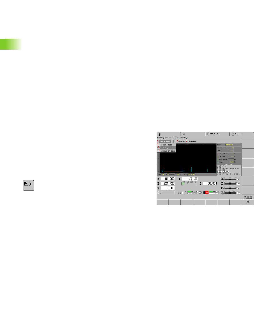
Analyzing reference machining
The load monitor shows the torque and the limit values of the selected
component over time.
Limit values gray: Nonmonitored area (hiding rapid traverse paths).
In addition the CNC PILOT displays the values of the cursor position
numerically.
Selection:
U
Selection: File button in the “Display and adjust load parameters”
dialog box.
U
Switch back to “Edit load parameters”