Axis designations and coordinate system, Machine reference points, 4 f undamentals – HEIDENHAIN CNC Pilot 4290 V7.1 User Manual
Page 40
40
1
.4 F
undamentals
Axis designations and coordinate system
Coordinate system
The meanings of the coordinates X, Y, Z, B, C are specified in DIN
66 217.
The coordinates entered for the principle axes X and Z are referenced
to the workpiece zero point. The angular data for the rotary axes B and
C are given with respect to the zero point of the respective rotary axis.
On lathes, C axis movements are realized by turning the workpiece
and B axis movements by tilting the tool (swivel head).
Axis designations
The cross slide is referred to as the X axis and the saddle as the Z
axis.
All X-axis values that are displayed or entered are regarded as
diameters. In TURN PLUS you can define whether the X axis values
are diameters or radii.
Lathes with Y axis: The Y axis is perpendicular to the X axis and Z axis
(Cartesian system).
When programming paths of traverse, remember to:
Program a positive value to depart the workpiece.
Program a negative value to approach the workpiece.
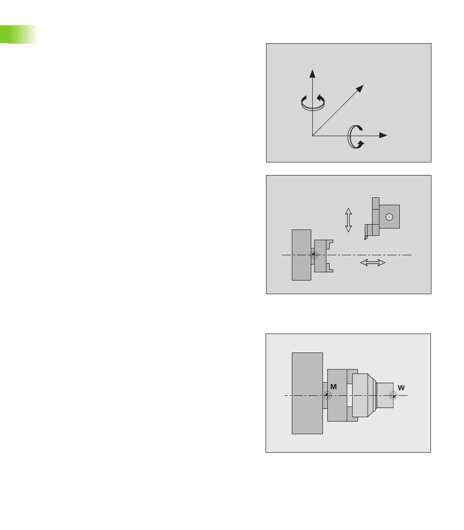
Machine reference points
Machine zero point
The point of intersection of the X and Z axes is called the machine
zero point. On a lathe, the machine zero point is usually the point of
intersection of the spindle axis and the spindle surface. The machine
zero point is designated with the letter “M”.
Workpiece zero point
For machining a workpiece, it is easier to reference all input data to a
zero point located on the workpiece. By programming the zero point
used in the workpiece drawing, you can take the dimensions directly
from the drawing, without further calculation. This point is the
“workpiece zero point.” The workpiece zero point is designated with
the letter “W”.
+Y
+X
+Z
+C
+B
M
Z
Z+
Y+
X
X+