Lateral surface: circular hole or figure pattern, 8 c-axis cont ours – HEIDENHAIN CNC Pilot 4290 V7.1 User Manual
Page 446
446
6.8 C-Axis Cont
ours
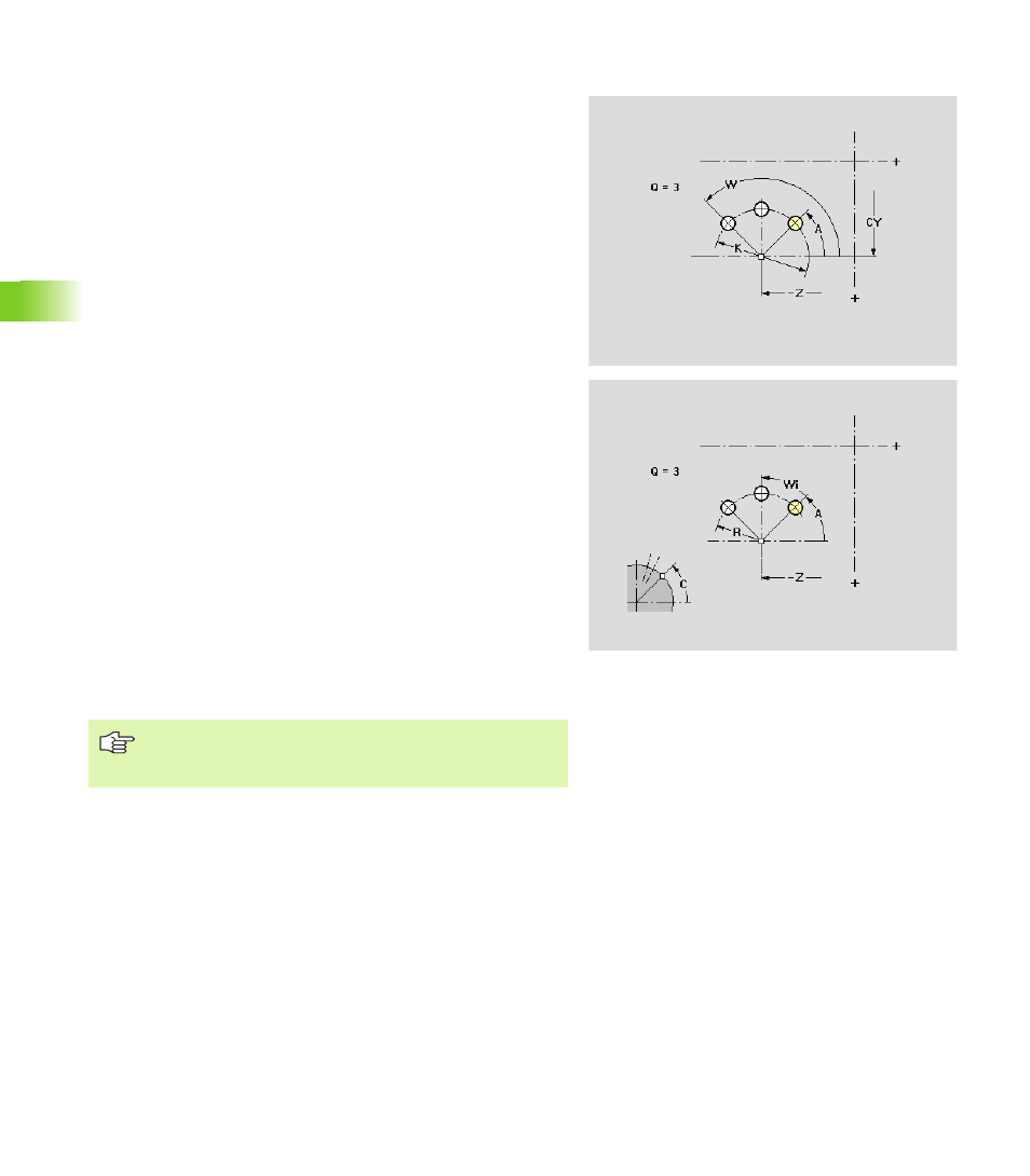
Lateral surface: Circular hole or figure pattern
This function defines a linear hole or figure pattern on the lateral
surface.
Parameters
Z
Center of pattern
CY
Center of pattern – angle as “linear dimension”
C
Center of pattern – angle
Q
Number of figures (default: 1)
Orientation
Clockwise
Counterclockwise
R
Radius of the pattern
K
Diameter of the pattern
A
Starting angle, position of the first figure (reference: Z axis)
If A and W are not programmed: Figures are arranged on a full
circle, starting at 0°
W
End angle, position of the last figure (reference: Z axis)
If W is not programmed: Figures are arranged on a full circle,
starting at A
Wi
Angle between two figures (algebraic sign has no effect)
Position of the figures
Normal position: The original figure is rotated about the
center of the pattern (rotation)
Original position: The position of the original figure is
maintained (translation)
Hole description/figure description
When defining patterns with circular slots, the “center of
curvature” is added to the pattern position (see “Circular
pattern with circular slots” on page 169).