Cycle specification – HEIDENHAIN CNC Pilot 4290 V7.1 User Manual
Page 498
498
6.14 Int
e
ra
ctiv
e W
o
rk
ing Plan Gener
a
tion (IWG)
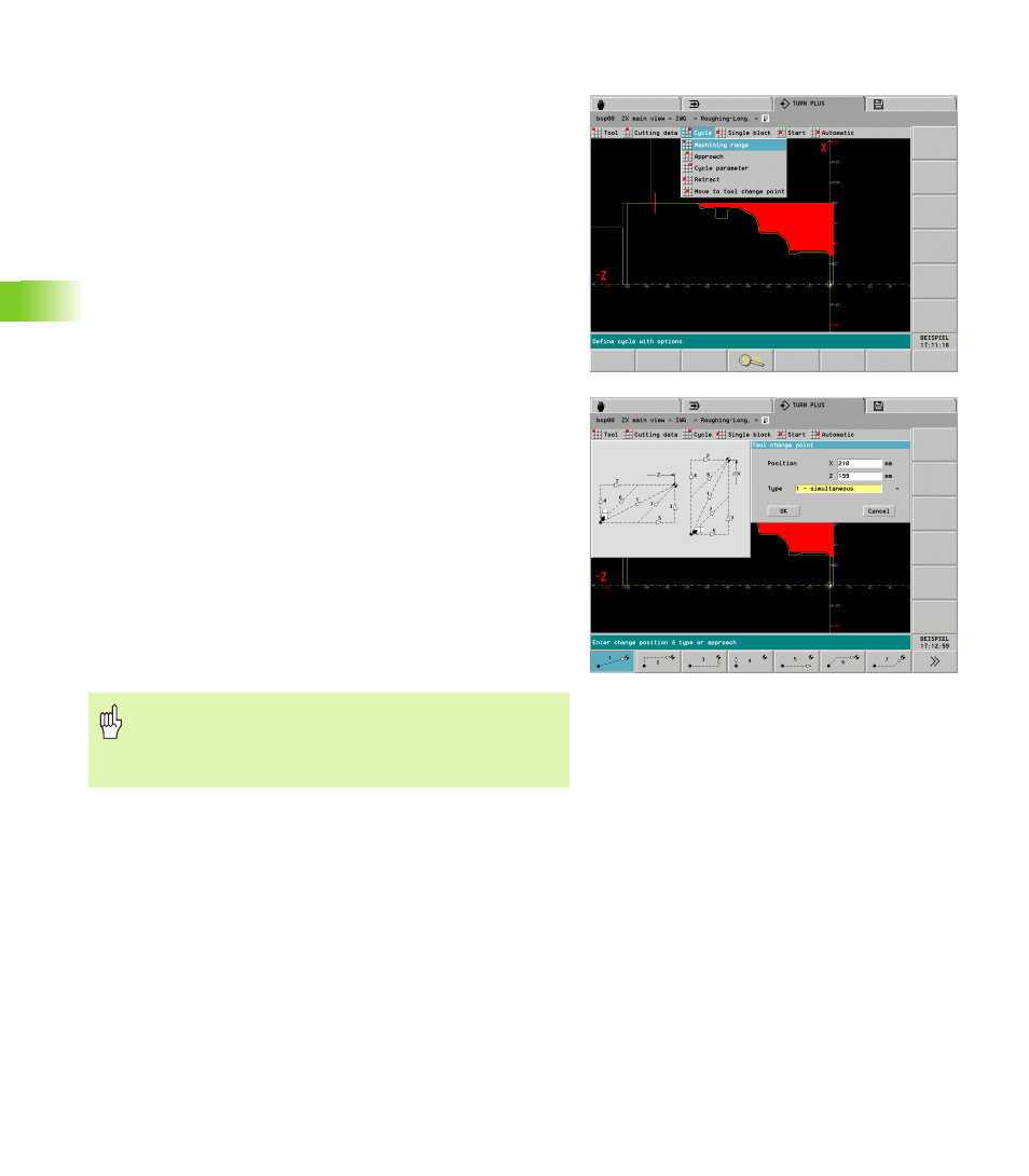
Cycle specification
In the “Cycle” drop-down menu, define the cycle parameters and the
strategies for approach and departure:
Machining range: Define the area to be machined and the
machining direction by area selection.
Selection by soft key: The sequence of selection defines the
machining direction.
Selection by touch pad – left mouse button: Machine in direction
of contour definition.
Selection by touch pad – right mouse button: Machine opposite to
direction of contour definition.
Approach: Before the cycle is called, the tool moves at rapid
traverse from the current position to the approach position. The
“Approach” function is not contained in drilling and threading
cycles. Place the tool on a suitable position using the “Approach”
function.
Cycle parameter: TURN PLUS suggests the cycle parameters.
Check/optimize the parameters.
Retract: After the cycle is finished, the tool moves at rapid traverse
to the retraction position.
Move to tool change point: After the cycle is finished or after
“Retract,” the tool moves to the change position. You define the
position to be approached and the traversing mode in “Traversing
mode to tool change position [WP]” (machining parameter 2):
WP=1: The position defined in the “Tool change point” dialog box
is approached with G0. TURN PLUS enters the tool change point
as a proposed value.
WP=2: TURN PLUS generates a G14. The position defined in the
“Tool change point” dialog box has no effect.
WP=3: TURN PLUS calculates the tool change point according to
the tools currently on the turret.
Danger of collision!
As frequently not all of the tools are known when you
generate a work block, you should not use the WP=3
setting (machining parameter 2) in the IWG.