9 c-axis contours— fundamentals, Milling contour position, 9 c-axis contours—fundamentals – HEIDENHAIN CNC Pilot 4290 V7.1 User Manual
Page 168
168
4.9 C-Axis Cont
ours—F
undamentals
4.9 C-Axis Contours—
Fundamentals
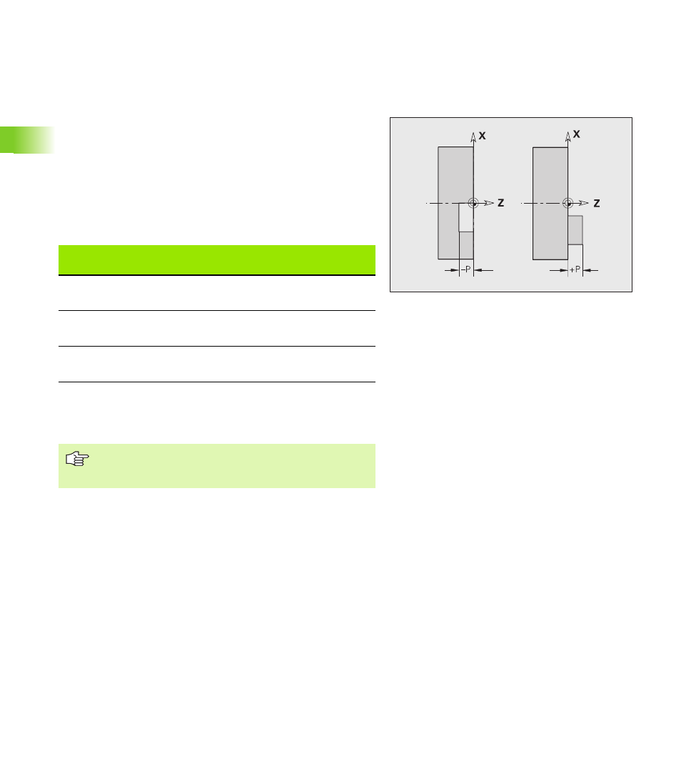
Milling contour position
Define the reference plane or the reference diameter in the section
code. Specify the depth and position of a milling contour (pocket,
island) in the contour definition:
With depth P programmed in the previous G308 cycle.
Alternatively on figures: Cycle parameter depth P.
The algebraic sign of “P” defines the position of the milling contour:
P<0: Pocket
P>0: Island
X: Reference diameter from the section code
Z: Reference plane from the section code
P: Depth from G308 or from cycle parameter
Contours in more than one plane (hierarchically nested contours):
A plane begins with G308 and ends with G309.
G308 defines a new reference plane/reference diameter. The first
G308 uses the reference plane defined in the section code. Each
following G308 defines a new plane. Calculation:
New reference plane = Reference plane + P (from previous G308)
G309 switches back to the previous reference plane.
Start pocket/island G308-Geo
G308 defines a new reference plane / reference diameter in
hierarchically nested contours.
Milling contour position
Section
P
Surface
Milling floor
STIRN [FRONT]
P<0
P>0
Z
Z+P
Z+P
Z
RUECKSEITE [REAR
SIDE]
P<0
P>0
Z
Z–P
Z–P
Z
MANTEL
[SURFACE]
P<0
P>0
X
X+(P*2)
X+(P*2)
X
The area milling cycles mill the surface specified in the
contour definition. Islands within this surface are not
taken into consideration.
Parameters
P
Depth for pocket, height for islands