Simulation window, 1 simulation mode of oper ation – HEIDENHAIN CNC Pilot 4290 V7.1 User Manual
Page 368
368
5.1 Simulation Mode of Oper
ation
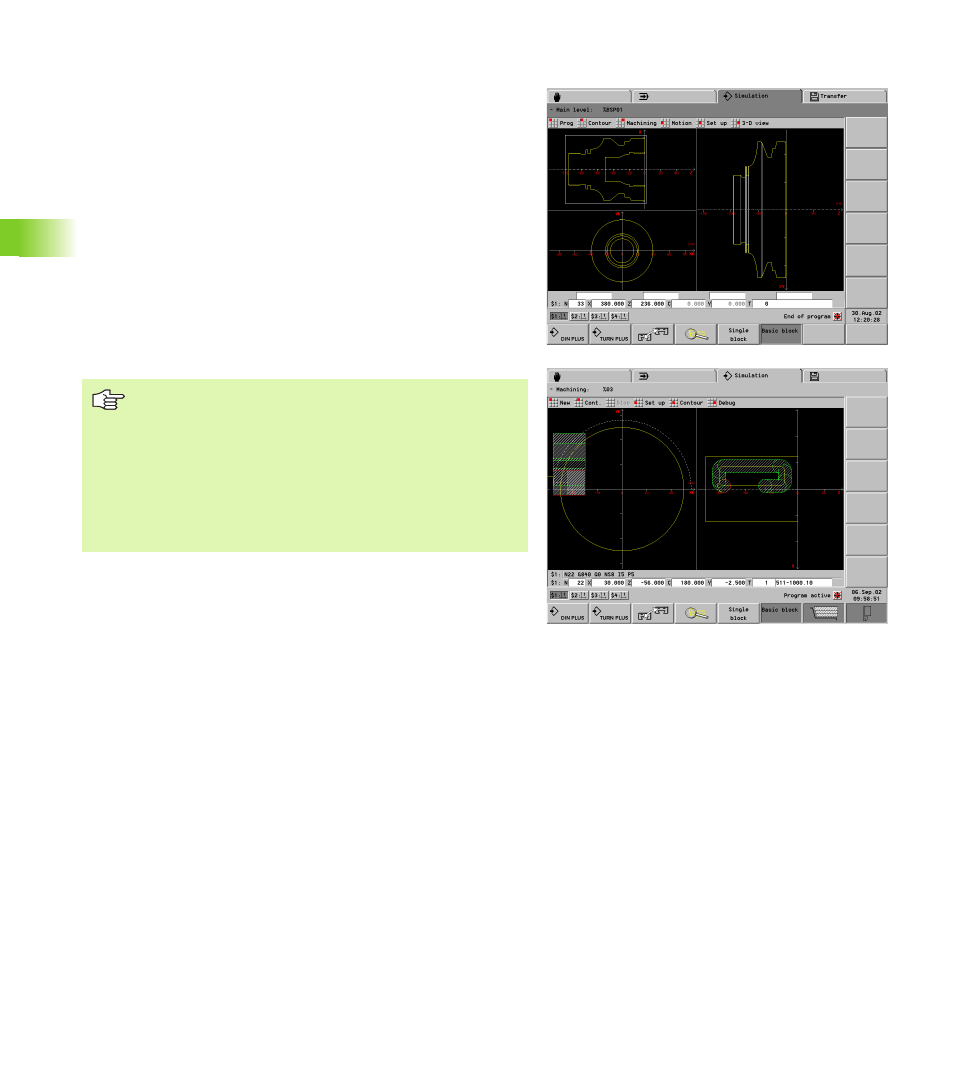
Simulation window
With the simulation windows described in the following you check not
only the turning work but also the drilling and milling operations.
Turning window: The turning contour is depicted in the XZ
coordinate system.
Front window: The contour and traverse paths are shown in the XY
plane, taking the spindle position into account. The spindle position
0° is located on the positive X-axis (designation: XK).
Surface window: The contour display and traverse-path display are
oriented to the position on the unrolled lateral surface (designation:
CY) and the Z coordinates. Contours on the lateral surface are
shown “on the workpiece surface.” (Contours of the lateral surface
are drawn on the milling floor in the graphic window of the DIN
PLUS editor.)
Side view (YZ): The contour and traverse path are shown in the YZ
plane. The side view depicts only the Y and Z coordinates—not the
spindle position (see figure below).
Front face and surface windows operate with a fixed
spindle position. Whereas the machine turns the
workpiece, the graphic simulation moves the tool.
The surface window and side view (YZ) are shown
alternatively.
The surface window is suited for simulation of drilling,
boring and milling operations with the C axis.
The side view is suited for simulation of the Y axis and
for operations on tilted planes.