Circular path g12/ g13, 13 simple linear and cir c ular mo v e ments – HEIDENHAIN CNC Pilot 4290 V7.1 User Manual
Page 191
HEIDENHAIN CNC PILOT 4290
191
4.13 Simple Linear and Cir
c
ular Mo
v
e
ments
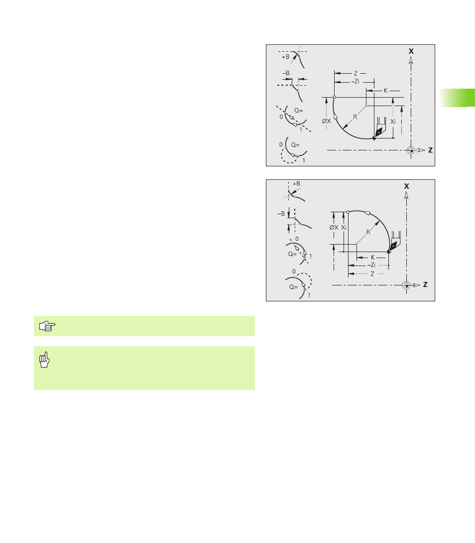
Circular path G12/ G13
G12/G13 moves the tool in a circular arc at the feed rate to the “end
point.” The center dimensioning is absolute. Direction of rotation (see
help graphic):
G12: In clockwise direction
G13: In counterclockwise direction
Parameters
X
End point (diameter)
Z
End point
R
Radius (0 < R <= 200 000 mm)
I
Absolute center point (radius)
K
Absolute center point
Q
Point of intersection. End point if the circular arc intersects a
line segment or another circular arc (default: 0):
Q=0: Near point of intersection
Q=1: Far point of intersection
B
Chamfer/rounding. Defines the transition to the next contour
element. When entering a chamfer/rounding, program the
theoretical end point.
No entry: Tangential transition
B=0: No tangential transition
B>0: Rounding radius
B<0: Chamfer width
E
Special feed factor for chamfer/rounding arc (default: 1)
Special feed rate = active feed rate * E (0 < E <= 1)
Programming X, Z: Absolute, incremental, modal or “?”
Danger of collision!
If V variables are used for calculating the address
parameters, a limited contour check is carried out. Ensure
that the variable values produce a circular arc.