Chucking equipment section – HEIDENHAIN CNC Pilot 4290 V7.1 User Manual
Page 142
142
4.4 Pr
ogr
am Section Code
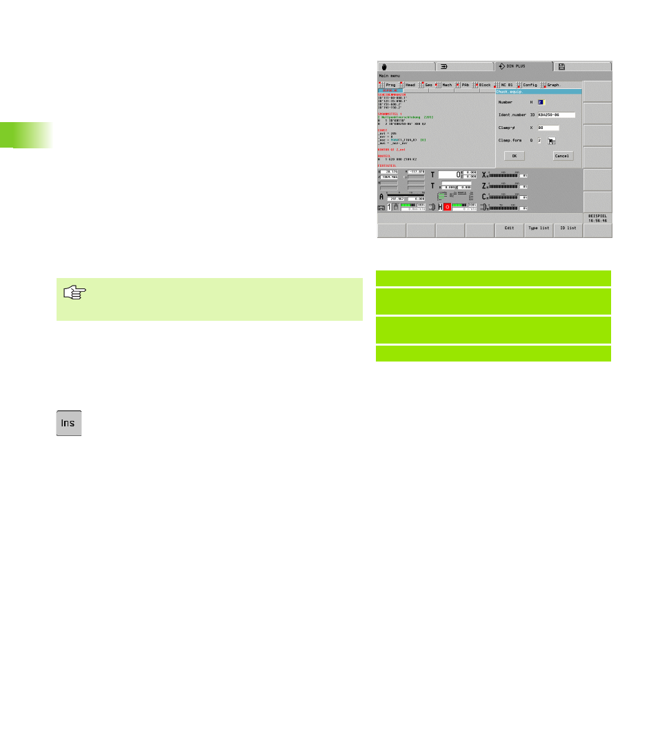
CHUCKING EQUIPMENT section
The CHUCKING EQUIPMENT x program section (x: 1 to 4) defines
spindle assignment x. Using the identification numbers of chuck, jaws
and adapters (lathe center, etc.), you create the chucking equipment
table.
Entering the chucking equipment data:
U
Select “Head > Chucking equipment.” The CNC
PILOT positions the cursor to the CHUCKING
EQUIPMENT section.
U
Position the cursor.
U
Press the INS key: The editor opens the “Slide
number” dialog box.
U
Edit the dialog box
Editing the chucking equipment data:
U
Position the cursor on the chucking equipment
U
Press ENTER
U
Edit the chucking equipment dialog box
Example: Chucking equipment table
SPANNMITTEL 1 [CHUCKING EQUIPMENT]
H1 ID"KH250"
[Chuck]
H2 ID"KBA250-77"
[Chuck jaws]
. . .
Parameters of the chucking equipment dialog box
H
Clamp number (reference for G65)
H=1: Chuck
H=2: Chuck jaw
H=3: Chuck supplement—spindle-side
H=4: Chuck supplement—tailstock side
ID
Identification number of chucking equipment (reference to
database).
X
clamping diameter of chuck jaw
Q
Clamping form of jaws (see G65)
The chucking equipment table is evaluated in the
simulation (G65). It has no influence on the machining
process.