2 contour simulation, Functions of the contour simulation, 2 cont our simulation 5.2 contour simulation – HEIDENHAIN CNC Pilot 4290 V7.1 User Manual
Page 374
374
5.2 Cont
our Simulation
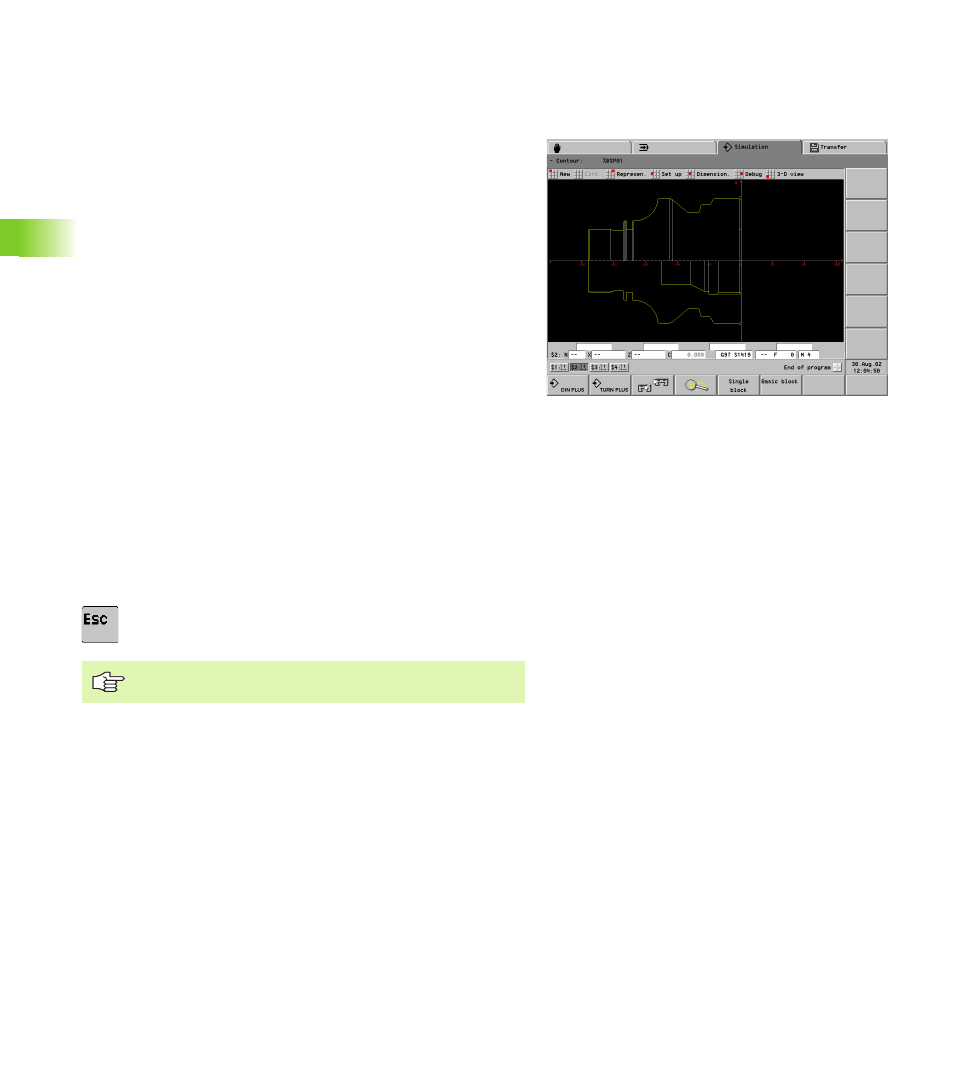
5.2 Contour Simulation
Functions of the contour simulation
Contour simulation presupposes that the blank or finished part contour
(blank or finished part definition, auxiliary contours) is programmed. If
the blank or finished part contours have not yet been completely
programmed, they are displayed as completely as possible.
The contour-simulation function allows you to:
Select between “section” or “view” graphics.
Check the contour programming through simulation in single blocks.
Check the parameters of a contour element (element
dimensioning).
Measure each contour point with respect to a reference point (point
dimensioning).
Controlling the contour simulation:
U
Select “New”: Re-simulates the contour (contour changes are taken
into account).
U
Select “Continue”: The simulation shows the next NC block or basic
block.
Contour depiction:
U
Select “Represen.”: The CNC PILOT opens the “Contour
representation” dialog box. Set:
(Cross-) “Section”
(Lateral) “View”
Section & View. “View” is used above the center of rotation,
“Section” is used below
U
To return to the main menu, press the ESC key
Additional functions:
Debug menu item: If you use variables for contour description,
check them with the debug functions: see “Simulation with starting
block” on page 383
“3-D view” menu item: see “3-D View” on page 382
In single or basic block mode, the “section” is shown.