Contour-parallel roughing g830, 20 cont our -based t u rn ing cy cles – HEIDENHAIN CNC Pilot 4290 V7.1 User Manual
Page 218
218
4.20 Cont
our
-Based T
u
rn
ing Cy
cles
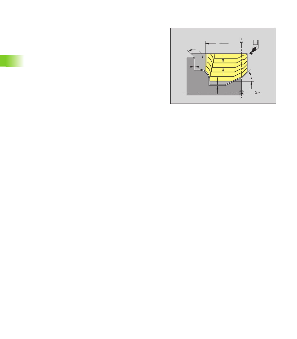
Contour-parallel roughing G830
G830 machines the area parallel to the contour from NS to NE as
defined by NS, NE. If required, the area to be machined is divided into
several sections (example: with contour valleys).
W
A
K
P
Z
X
Z
I
Ø
X
Ø
Parameters
NS
Starting block number (beginning of contour section)
NE
End block number (end of contour section)
NE not programmed: The contour element NS is machined
in the direction of contour definition.
NS=NE programmed: The contour element NS is machined
opposite to the direction of contour definition.
P
Maximum infeed
I
Oversize in X direction (diameter value) – (default: 0)
K
Oversize in Z direction (default: 0)
X
Cutting limit in X direction (diameter value) – (default: no
cutting limit)
Z
Cutting limit in Z direction (default: no cutting limit)
A
Approach angle (reference: Z-axis) – (default: 0°/180°, parallel
to Z-axis)
W
Departing angle (reference: Z-axis) – (default: 90°/270°;
perpendicular to Z-axis)
Q
Type of retraction at cycle end (default: 0)
Q=0: Return to starting point (first X, then Z direction)
Q=1: Positions in front of the finished contour
Q=2: Retracts to safety clearance and stops
V
Identifier beginning/end (default: 0)
A chamfer/rounding arc is machined:
V=0: At start and end
V=1: At start
V=2: At end
V=3: No machining
V=4: Chamfer/rounding arc is machined—not the basic
element (prerequisite: Contour section with one element)