Linear and rotary axes, 1 din pr ogr a mming – HEIDENHAIN CNC Pilot 4290 V7.1 User Manual
Page 110
110
4.1 DIN Pr
ogr
a
mming
Linear and rotary axes
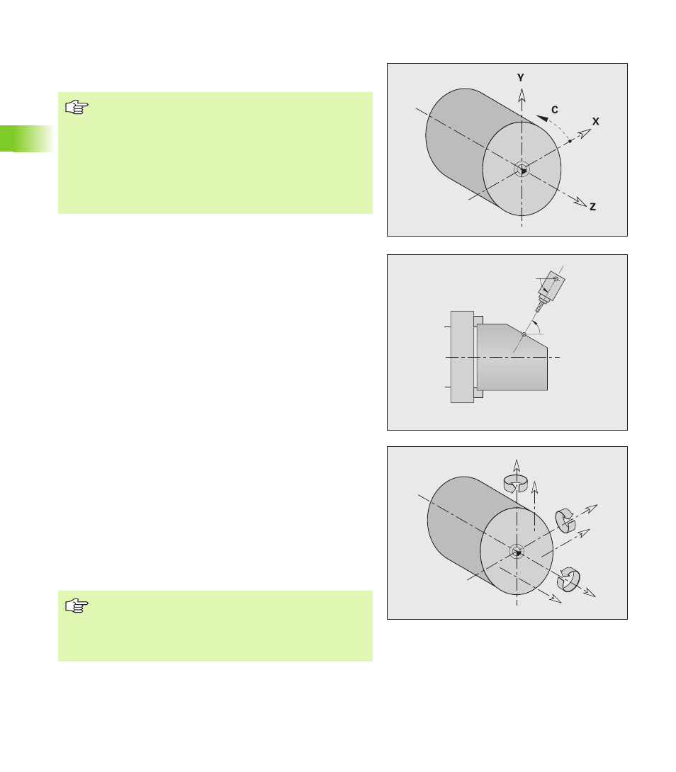
Principal axes: Coordinates of the X, Y and Z axes refer to the
workpiece zero point.
C axis as reference axis:
Angle data are with given respect to the zero point of the C axis.
C-axis contours and C-axis operations:
Positions on the front/rear face are entered in Cartesian
coordinates (XK, YK), or polar coordinates (X, C)
Positions on the lateral surface are entered in polar coordinates (Z,
C). Instead of C, the linear value CY is used (“unrolled” reference
diameter).
B axis—tilted working plane: The B axis makes it possible to drill,
bore and mill in oblique planes. The coordinate system is tilted for
programming in such a way that you can define the drilling patterns
and milling contours in the YZ plane. Machining is then conducted in
the tilted plane.
Secondary axes (auxiliary axes): In addition to the principal axes, the
CNC PILOT supports:
U:Linear axis in X direction
V:Linear axis in Y direction
W:Linear axis in Z direction
A:Rotary axis that rotates about X
B:Rotary axis that rotates about Y
C:Rotary axis that rotates about Z
The auxiliary axes are only programmed in the MACHINING section,
using the functions G0 to G3, G12, G13, G30, G62 and G701. A circular
interpolation is only possible in the principal axes. Rotary axes
(auxiliary axes) are programmed in the MACHINING section, using
G15.
B
B
Z
Y
X
A
B
C
U
V
W
Remember about negative X coordinates
Not allowed with contour descriptions
Not allowed for turning cycles
The contour follow-up is switched off
The direction of rotation for circular arcs (G2/G3, G12/
G13) has to be set manually
The position of the tool radius compensation (G41/G42)
has to be set manually
The DIN editor respects only address letters of the
configured axes.
The behavior of the rotary axes B and C depends on
whether they have been configured as principal or
auxiliary axes.