6 basic contour elements, Starting point of turning contour g0-geo, Line segment in a contour g1-geo – HEIDENHAIN CNC Pilot 4290 V7.1 User Manual
Page 147
HEIDENHAIN CNC PILOT 4290
147
4.6 Basic Cont
our Elements
4.6 Basic Contour Elements
Starting point of turning contour G0-Geo
G0 defines the starting point of a turning contour.
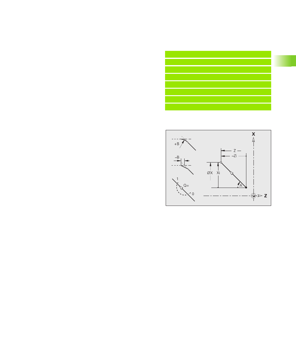
Line segment in a contour G1-Geo
G1 defines a line segment in a turning contour.
Example: G0-Geo
. . .
FERTIGTEIL [FINISHED PART]
N2 G0 X30 Z0
[starting point of contour]
N3 G1 X50 B-2
N4 G1 Z-40
N5 G1 X65
N6 G1 Z-70
. . .
Parameters
X
Contour starting point (diameter value)
Z
Contour starting point
Parameters
X
End point of contour element (diameter value)
Z
End point of contour element
A
Angle to rotary axis (for angle direction see graphic support
window)
Q
Point of intersection. End point if the line segment intersects a
circular arc (default: 0):
Q=0: Near point of intersection
Q=1: Far point of intersection
B
Chamfer/rounding. Defines the transition to the next contour
element. When entering a chamfer/rounding, program the
theoretical end point.
No entry: Tangential transition
B=0: No tangential transition
B>0: Rounding radius
B<0: Chamfer width
E
Special feed rate for the chamfer/rounding arc during the
finishing cycle (default: 1)
Special feed rate = active feed rate * E (0 < E <= 1)