Contour checking, 4 motion simulation – HEIDENHAIN CNC Pilot 4290 V7.1 User Manual
Page 381
HEIDENHAIN CNC PILOT 4290
381
5.4 Motion Simulation
Protection zone and limit switch monitoring
(motion simulation)
You set the monitoring of protection zones and limit switch as follows:
U
“Set up > Protection zone > Monitoring off”: The protection zones/
limit switches are not monitored.
U
Select “Set up > Protection zone > Monitoring with warning”: The
CNC PILOT registers protection-zone or limit-switch violations and
treats them as warnings. The NC program is simulated up to the end
of program.
U
Select “Set up > Protection zone > Monitoring with error”: A
protection zone or limit switch violation results in an immediate error
message and cancelation of the simulation.
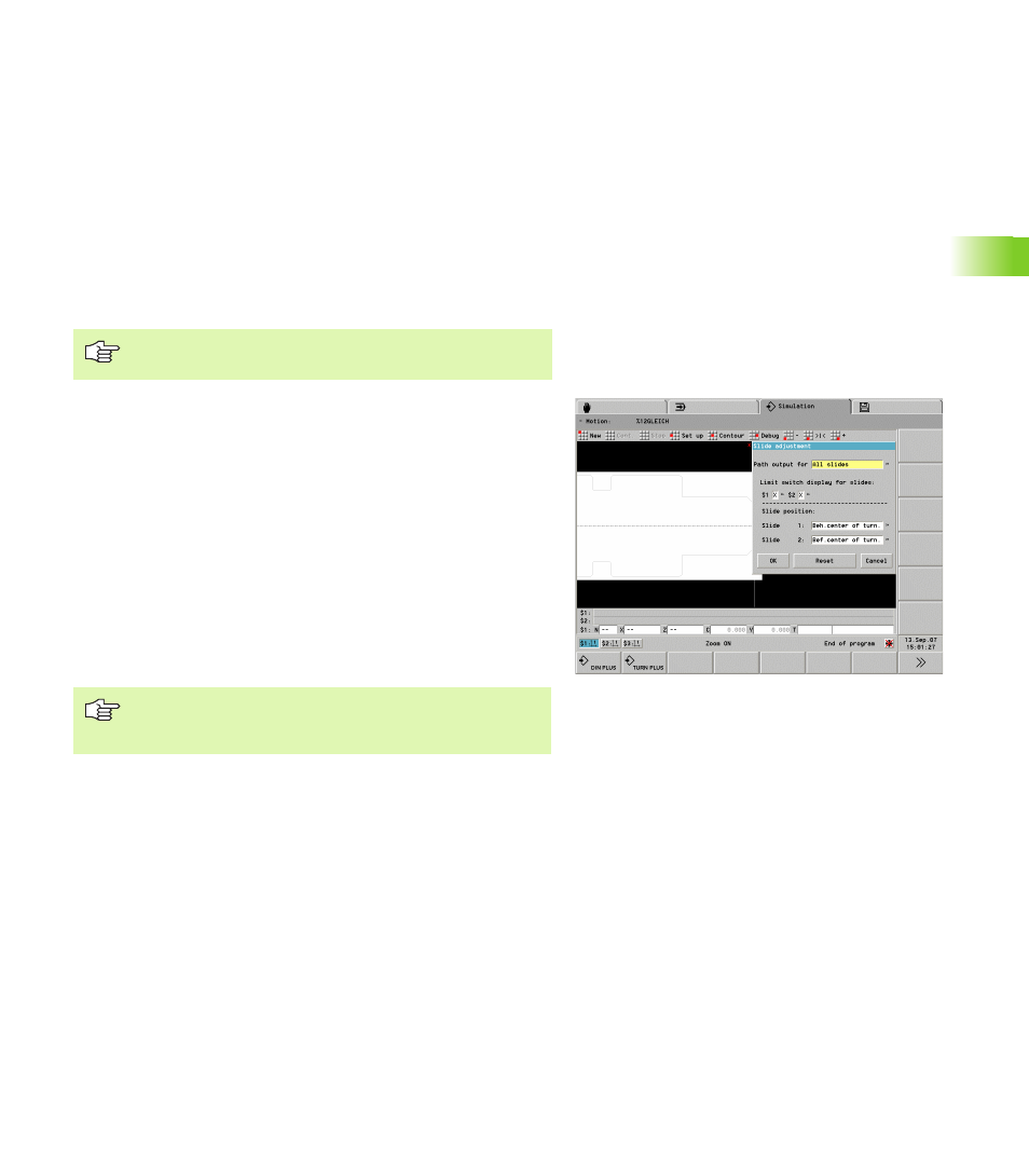
Visual limit-switch and protection-zone monitoring
U
Select “Set up > Slide”: The CNC PILOT opens the “slide settings”
dialog box.
U
In the “Limit switch display for slides input fields...,” specify which
limit switches are to be displayed.
Depending on this setting, the motion simulation shows the Software
limit switch or the protection zone with respect to the tool tip. That
simplifies monitoring the traverse paths near the working space limits.
The visual monitoring is independent from the protection zone
monitoring and limit switch monitoring.
The simulation draws a rectangle resulting from the limit switches and
the protection zone. The smaller of the dimensions are depicted. If a
limit switch defines a side of the rectangle, the line is shown in red. If
the protection zone defines a side, the line is red/white.
Contour checking
With the functions of the “Contour” menu you can switch to contour
dimensioning or to the 3-D view.
Displays the contour according to its current state of progress:
U
Select “Contour > Dimensioning”: The simulation activates the
element and point dimensioning (see “Contour dimensioning” on
page 375).
3-D view
U
Select “Contour > 3-D view”: The simulation switches to 3-D view
(see “3-D View” on page 382).
You define the protection zone dimensions in the setup
mode. They are managed in MP 1116, ....
The simulation shows the limit switch dimensions with
respect to the tool point. This is why the limit switch
dimensions are repositioned in a tool change.