Configuring windows (views), Configuring the control graphics, 1 7 configur ing turn plus – HEIDENHAIN CNC Pilot 4290 V7.1 User Manual
Page 550
550
6.1
7
Configur
ing TURN PLUS
Configuring windows (views)
Define the views that TURN PLUS is to depict besides the main view
(XZ plane).
Selection:
U
Select “Configuration > Change.”
U
Press “Views.” TURN PLUS opens the “Window configuration”
dialog box.
“Window configuration” dialog box
Views: Display of the selected views
Selection: Select the views you want to display
Mirror main view?
Yes: Display the complete contour
No: Display the contour above the turning center
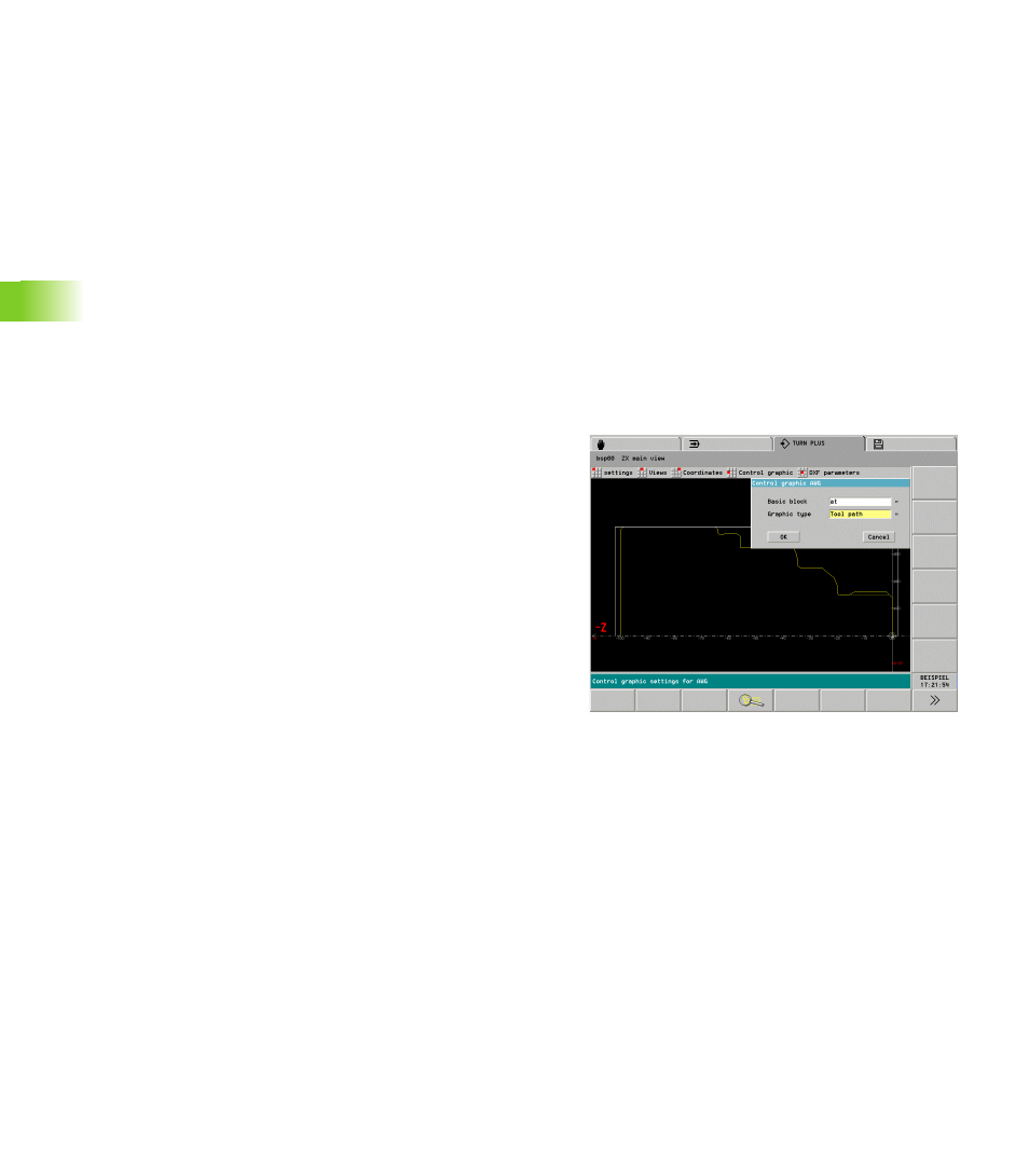
Configuring the control graphics
With these configuration functions you edit the sequence of the
control graphics and the display of the paths of traverse.
Selection:
U
Select “Configuration > Change.”
U
Select “Control graphic > IWG” (or “.. > AWG”). TURN PLUS opens
the “Control graphic IWG/AWG” dialog box.
“Control graphic IWG/AWG” dialog box
Basic block:
On: The control graphic stops after each path of traverse. Press
the “Continue” soft key to start the next path of traverse.
Off: The control graphic simulates the machining operation
without any interruptions.
Graphic type:
Tool path: The control graphic depicts paths of traverse with solid
line (reference: theoretical tool tip).
Cutting path: The control graphic depicts the surface traversed by
the “cutting area” of the tool with hatch marks. The cutting path
graphic accounts for the exact geometry of the tool tip (cutting
radius, cutting width, tool-tip position, etc.). This graphic display is
based on the tool data.
Material removal graphics: The blank is displayed as a white
surface which is “cut” during machining.