Pontoon, Linear superimposition (“linear overlay”), 7 ov er la y elements – HEIDENHAIN CNC Pilot 4290 V7.1 User Manual
Page 419
HEIDENHAIN CNC PILOT 4290
419
6.7 Ov
er
la
y Elements
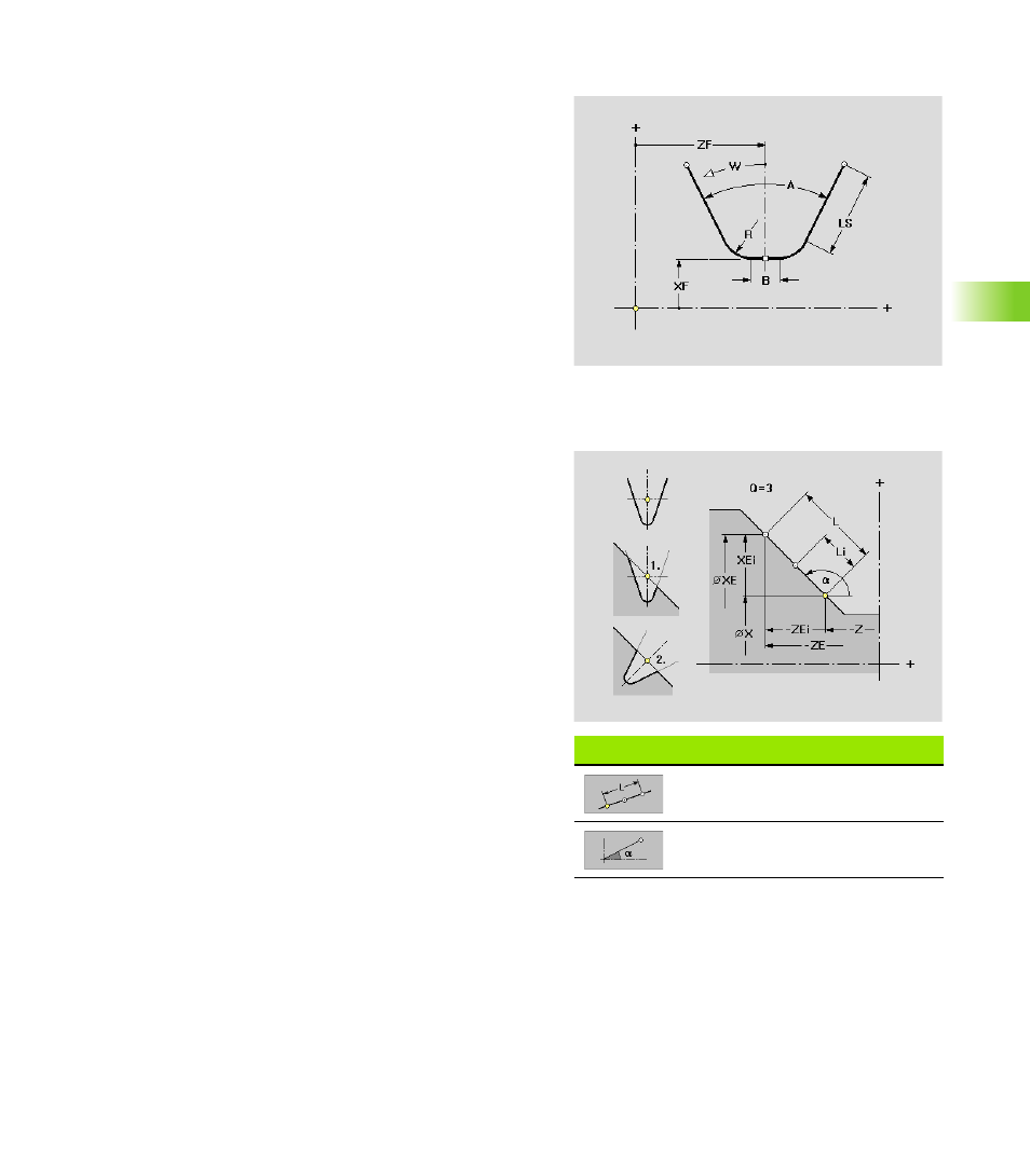
Pontoon
Reference point: Center of base element
Linear superimposition (“linear overlay”)
Parameters
XF
Reference point shift
ZF
Reference point shift
R
R>0: Rounding radius
R=0: No rounding
A
Angular length
LS
Length of wedge sides (projecting element parts are cut at
the “points of overlay”)
B
Width of base element
W
Angle of rotation: The overlay contour is rotated by the “angle
of rotation.”
“Linear overlay” soft keys
Enter the length (instead of end
point)
Enter the angle
Parameters
X
Starting point, position of the first overlay element
Z
Starting point, position of the first overlay element
Position (see illustration)
1: Original position: Inserts the overlay contour in the
supporting contour “as is.”
2: Normal position: Rotates the overlay contour about the
slope angle of the supporting contour element and then
inserts it in the supporting contour.
Q
Number of overlay elements
XE
End point, position of the last overlay element
ZE
End point, position of the last overlay element
XEi
Incremental end point
ZEi
Incremental end point
L
Distance between the first and last overlay element
Li
Distance between the overlay elements
a
Angle (default: Angle of the supporting contour element)