27 milling cy cles – HEIDENHAIN CNC Pilot 4290 V7.1 User Manual
Page 263
HEIDENHAIN CNC PILOT 4290
263
4.27 Milling Cy
cles
Program D and V to machine parts of a figure.
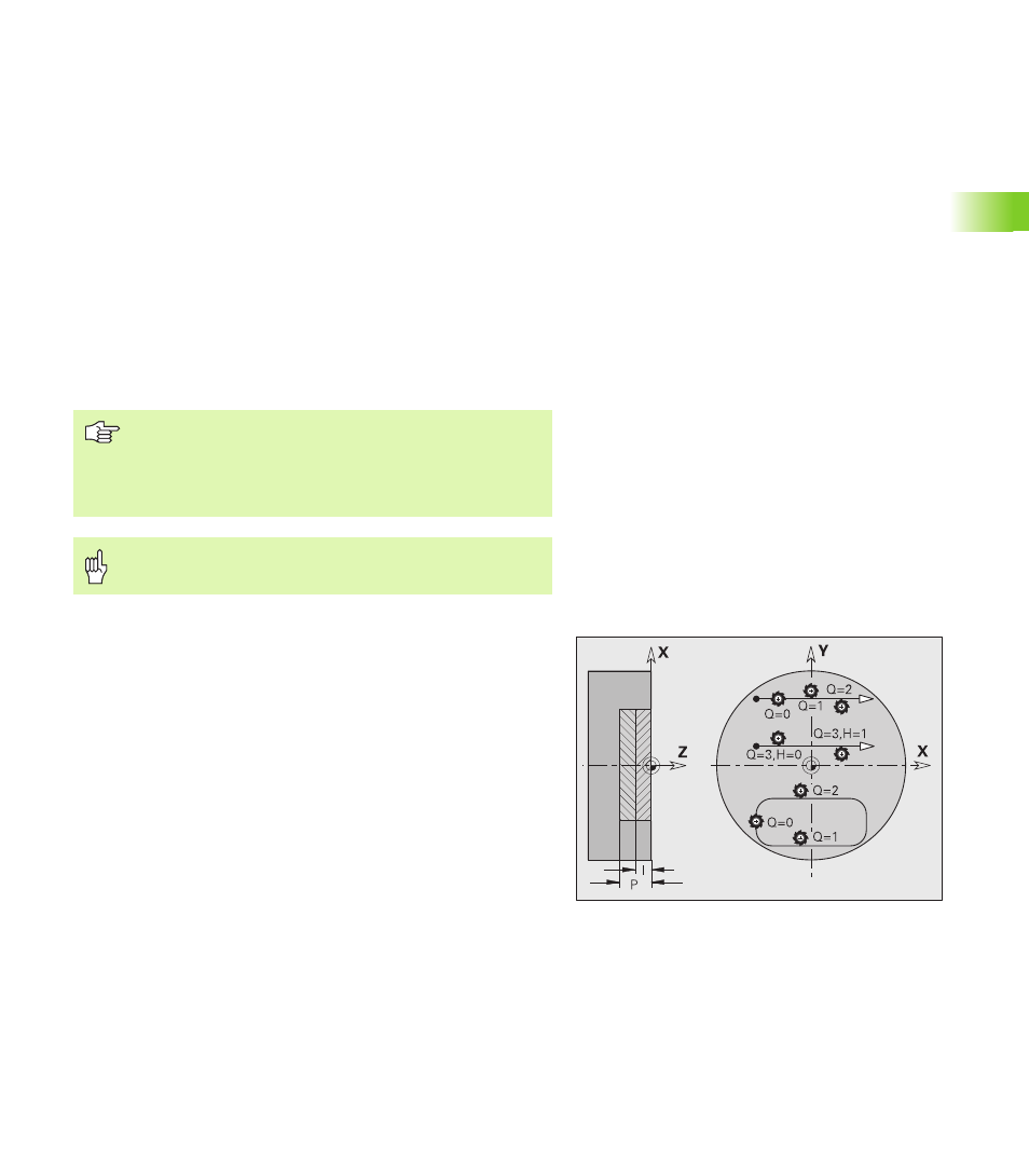
G840 – Milling
You can change the machining direction and the cutter radius
compensation (TRC) with the cycle type Q, the cutting direction H and
the rotational direction of the tool (see following table). Program only
the parameters given in the following list.
See also:
G840—Fundamentals: Page 261
G840—Calculating hole positions: Page 262
D
Starting element number for partial figures
The direction of contour definition for figures is
counterclockwise. The first contour element for figures:
Circular slot: The larger arc
Full circle: The upper semicircle
Rectangles, polygons and linear slots: The position angle
points to the first contour element.
V
Ending element number for partial figures
A
Sequence for “Calculate hole positions”: A=1
NF
Position mark – reference at which the cycle stores the hole
positions [1..127].
WB
Rework diameter—diameter of the milling cutter
The cycle takes the diameter of the active tool into
account when calculating the hole positions. Therefore,
you need to insert the drill before calling “G840 A1 ..”.
Program oversizes for calculating the hole positions and
for milling.
G840 overwrites any hole positions that may still be stored
at the reference “NF.”
Parameters – Calculating hole positions