Graphic elements, Displays, 1 simulation mode of oper ation – HEIDENHAIN CNC Pilot 4290 V7.1 User Manual
Page 364
364
5.1 Simulation Mode of Oper
ation
Graphic elements
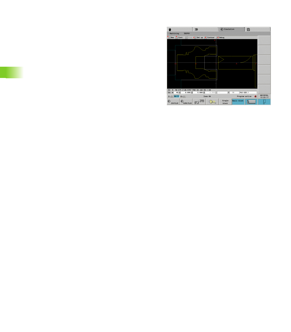
Coordinate systems: The zero point of the coordinate system
corresponds to the workpiece zero point. The arrows of the X and Z
axes point in the positive direction. If the NC program is machining
more than one workpieces, the coordinate systems of all required
slides are displayed.
Workpiece blank depiction
Programmed: Programmed blank
Not programmed: standard blank from control parameter 23.
Finished part depiction (and auxiliary contours)
Programmed: Programmed finished part
Not programmed: No display
Tilted plane: The simulation depicts the tilted plane as auxiliary
contour, if it is programmed with SURFACE_Y ...
Tool display. The CNC PILOT uses the parameters of the tool
database to display a tool. Whether the complete tool or only the
cutting area is shown is specified in “Picture number” (picture
no.=–1: No tool displayed).
In the NC program, the tool programmed in the TURRET section
is used
Not programmed in the NC program: The entry from the tool list
is used
Chucking equipment depiction: The simulation graphics depict
the chucking equipment provided that it has been programmed with
G65.
The CNC PILOT uses the parameters of the chucking equipment
database to depict a chuck.
Light dot: The light dot (small white square) represents the
theoretical tool tip.
Displays
The block display displays the programmed NC blocks (NC source
blocks). In the “Window selection” dialog box you specify (see
“Simulation window” on page 368):
Block display for the specified slides
Block display for the slides marked in the “Window selection”
dialog box
As an alternative to the block display the simulation displays four
variables: see “Debugging Functions” on page 383