Circular arc of turning contour g12/g13-geo, 6 basic cont our elements – HEIDENHAIN CNC Pilot 4290 V7.1 User Manual
Page 150
150
4.6 Basic Cont
our Elements
Example: G2-, G3-Geo
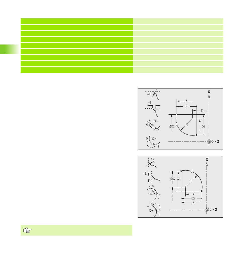
Circular arc of turning contour G12/G13-Geo
G12/G13 defines a circular arc in a contour with absolute center
dimensioning. Direction of rotation (see help graphic):
G12: In clockwise direction
G13: In counterclockwise direction
. . .
FERTIGTEIL [FINISHED PART]
N1 G0 X0 Z-10
N2 G3 X30 Z-30 R30
Target point and radius
N3 G2 X50 Z-50 I19.8325 K-2.584
Target point and center, incremental
N4 G3 XI10 ZI-10 R10
Target point (incremental) and radius
N5 G2 X100 Z? R20
Unknown target point coordinate
N6 G1 XI-2.5 ZI-15
. . .
Parameters
X
End point of contour element (diameter value)
Z
End point of contour element
I
Center (radius dimension)
K
Center
R
Radius
Q
Point of intersection. End point if the circular arc intersects a
line segment or another circular arc (default: 0):
Q=0: Near point of intersection
Q=1: Far point of intersection
B
Chamfer/rounding. Defines the transition to the next contour
element. When entering a chamfer/rounding, program the
theoretical end point.
No entry: Tangential transition
B=0: No tangential transition
B>0: Rounding radius
B<0: Chamfer width
E
Special feed rate for the chamfer/rounding arc during the
finishing cycle (default: 1)
Special feed rate = active feed rate * E (0 < E <= 1)
Programming X, Z: Absolute, incremental, modal or “?”