3 workpiece description, Entering the workpiece blank contour – HEIDENHAIN CNC Pilot 4290 V7.1 User Manual
Page 396
396
6.3 W
o
rk
piece Descr
iption
6.3 Workpiece Description
You program a contour by entering individual contour elements one
after the other in the correct sequence. You define the contour
elements using absolute, incremental, Cartesian or polar coordinates.
You can usually program a contour with the dimensions given in the
workpiece drawing.
TURN PLUS automatically calculates all missing coordinates, points of
intersection, center points, etc. that can be derived mathematically. If
the entered data permit several possible solutions, you can inspect the
individual solutions and select the proposal that matches the drawing.
You can import the following contours if they are available in DXF
format (see “Importing of DXF Contours” on page 458):
Workpiece blanks
Finished parts
Contour trains
Milling contours
Entering the workpiece blank contour
To describe the workpiece blank, proceed as follows:
Standard forms (bars, pipes): Definition with workpiece blank
macros
Complex workpiece blanks: Description as for finished part
Cast or forged blanks are generated from the finished part and the
oversize
Additional information:
see “Contours of Workpiece Blanks” on page 402
see “Attributes for workpiece blanks” on page 470
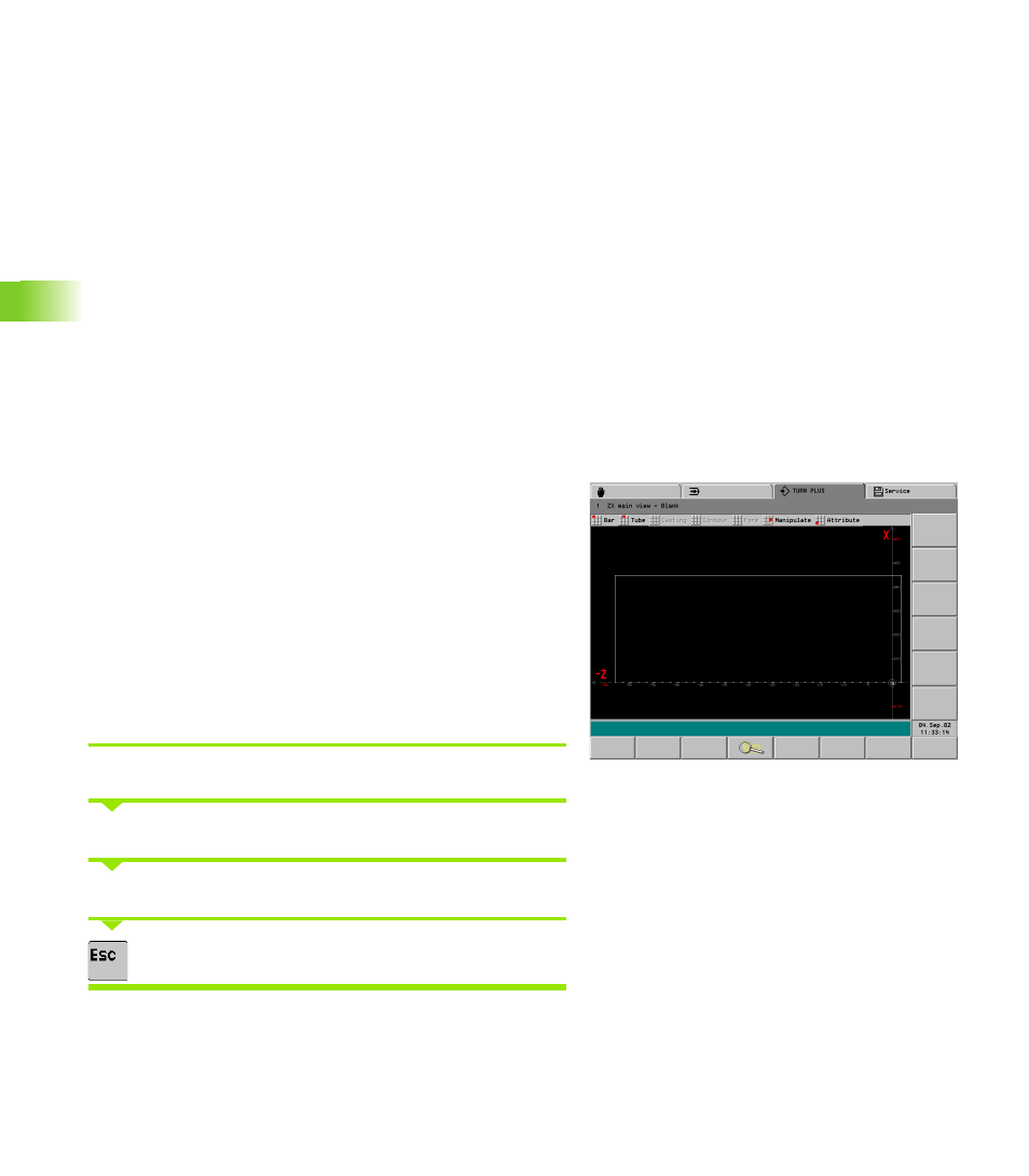
Entering the workpiece blank contour
Select “Workpiece > Blank > Bar” (“.. > Tube” or “.. > Casting”).
Enter the dimensions of the workpiece blank or oversize.
The CNC PILOT displays the workpiece blank.
Press the ESC key to return to the main menu.