5 tool dimensions, 5 t o ol dimensions 1.5 tool dimensions – HEIDENHAIN CNC Pilot 4290 V7.1 User Manual
Page 43
HEIDENHAIN CNC PILOT 4290
43
1
.5 T
o
ol Dimensions
1.5 Tool Dimensions
The CNC PILOT requires information on the specific tools for a variety
of tasks, such as calculating the cutting radius compensation or the
proportioning of cuts.
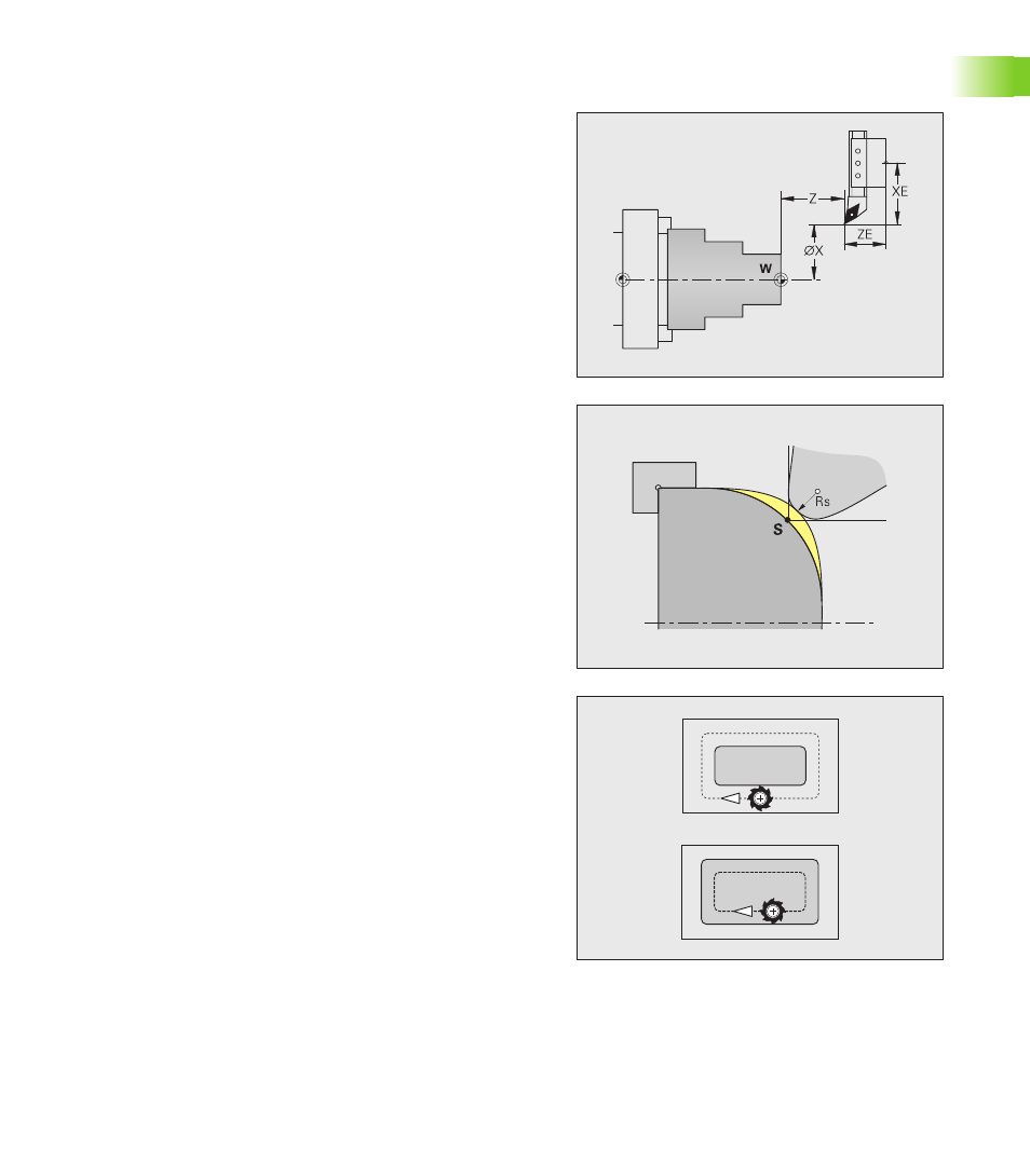
Tool dimensions:All position values that are programmed and
displayed are referenced to the distance between the tool tip and
workpiece zero point. Since the control only knows the absolute
position of the tool carrier (slide), The CNC PILOT needs the
dimensions XE and ZE to calculate and display the position of the tool
tip, and for Y axis machining, it also needs the dimension in Y.
Tool compensation: The tool tip is subjected to wear during
machining processes. To compensate for this wear, the CNC PILOT
uses compensation values. The system automatically adds the
compensation values to the values for length.
Tool radius compensation (TRC): The tip of a lathe tool has a certain
radius. When machining tapers, chamfers and radii, this results in
inaccuracies which the CNC PILOT compensates with its cutting
radius compensation function.
Programmed paths of traverse are referenced to the theoretical tool
tip S. The TRC function compensates for this error by calculating a
new path of traverse, the equidistant line.
Milling cutter radius compensation (MCRC):In milling operations,
the outside diameter of the milling cutter determines the contour.
When the MCRC function is not active, the system defines the center
of the cutter as the zero point for paths of traverse. The MCRC
function compensates for cutter radius by calculating a new path of
traverse, the equidistant line.