Yaskawa MP940 Reference Manual User Manual
Page 144
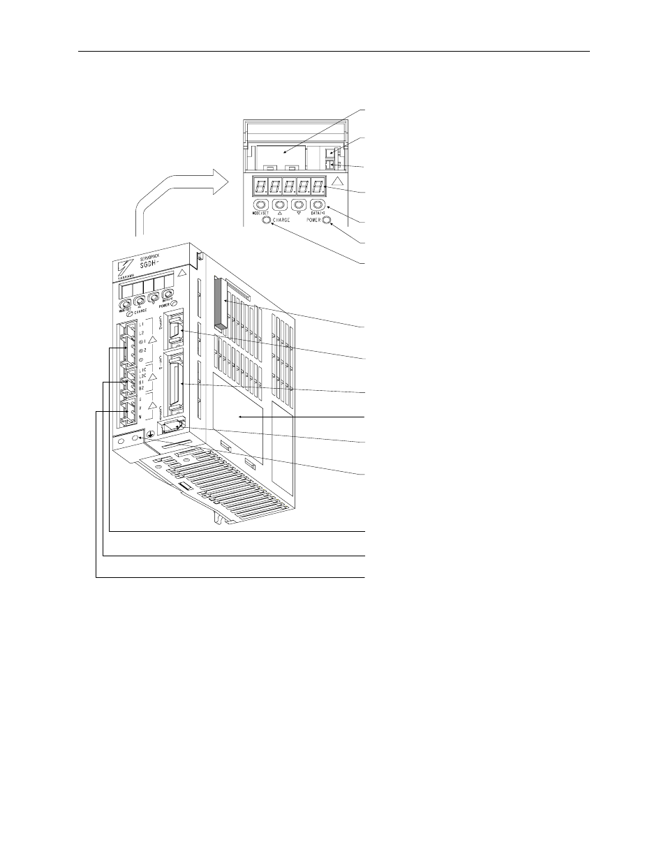
Handling Each Part
MotionSuite™ MP940 Machine Controller Reference Manual
5-2
Battery Holder
This stores the backup battery when an absolute encoder is
used.
Analog Monitor Connector (CN5)
This enables monitoring of the motor speed, torque
reference, etc., through the use of a dedicated cable.
Battery Connector (CN8)
This connector connects the absolute encoder backup battery.
Panel Display
This 5-digit 7-segment LED is used to display servo status
and alarm numbers, as well as during user parameter input.
Panel Switch
Used during user parameter setting.
Power ON Lamp
Lights when braking power is fed.
Charge Lamp
Lights when main power is fed. This lamp remains ON while a
charge remains in the main capacitor following power OFF. DO
NOT touch the servo amplifier at this time.
Option Unit Connector (CN10)
This connector connects option units for function expansion.
PC Monitor Connector (CN3)
This connector connects a PC monitor connector (CN3) either
for PC communication or a digital operator.
I/O Signal Connector (CN1)
This is the connector for command input signals and sequence I/O
signals.
Nameplate
The nameplate shows the servo amplifier model and ratings.
Encoder Connector (CN2)
This connector connects with the encoder mounted on the
servo motor.
Ground Terminal
This is a grounding terminal for protection against electric shock.
ALWAYS be sure to connect this.
Main Power Terminal
This is the main power input terminal.
Braking Power Terminal
This terminal connects to the prake power or an external
regen resistor.
Servo Motor Connection Terminal
This terminal connects to the servo motor power line.