Handling the mp940 module – Yaskawa MP940 Reference Manual User Manual
Page 145
Advertising
MotionSuite™ MP940 Machine Controller Reference Manual
Handling Each Part
5-3
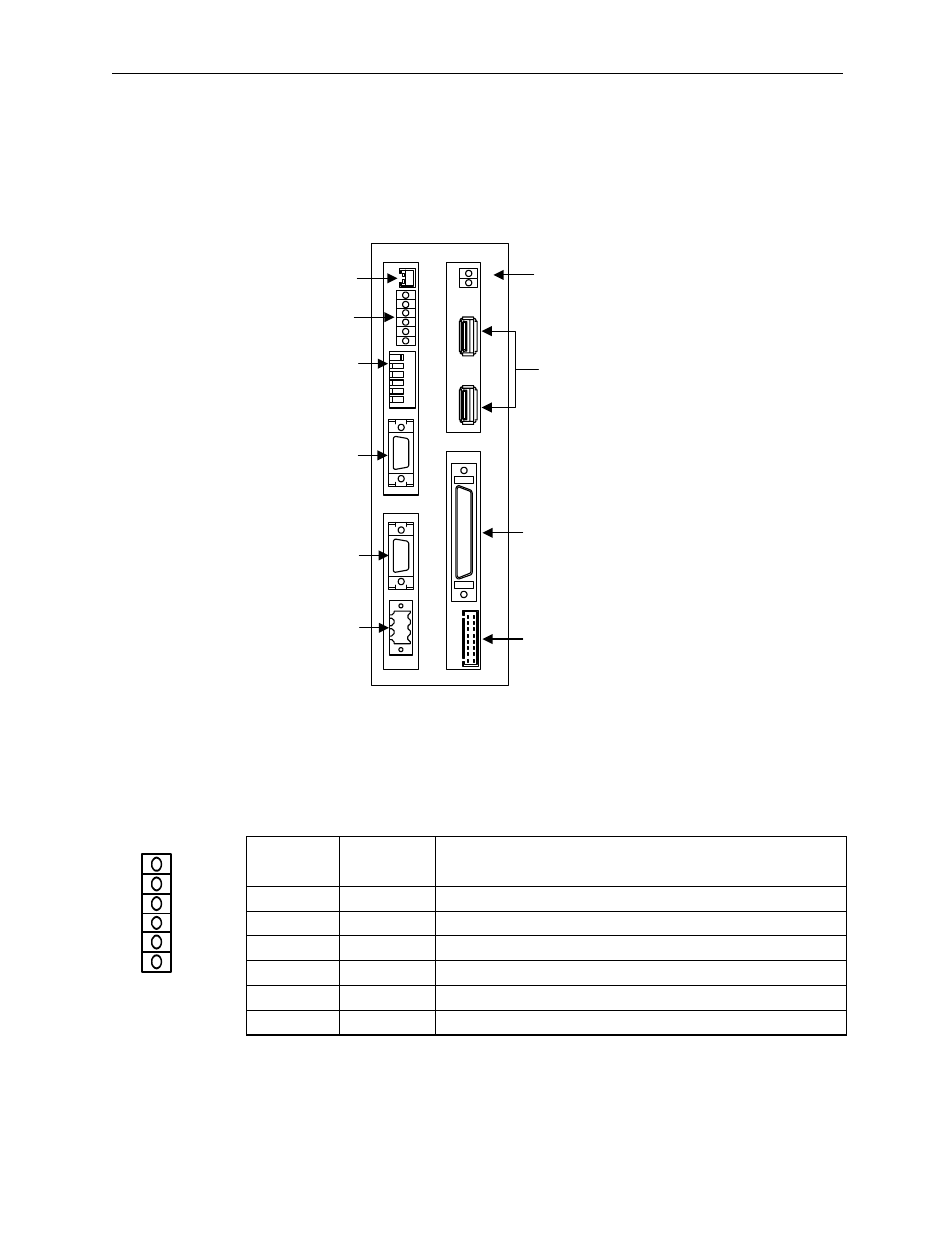
Handling the MP940 Module
An external view of the MP940 module (MC400) is shown below.
LED 1 shows the module status
Name
Display
Light Color
Meaning when Lit
RDY
Green
System normal
RUN
Green
Program running
ERR
Red
On/Flashing (or ON) at minor (or major) system fault/error
BAT
Red
On at battery voltage drop
PRT 1
Green
Transmitting to Serial Port 1
PRT 2
Green
Transmitting to Serial Port 2
BAT
RDY
RUN
ALM
BAT
PRT1
6
5
4
3
2
1
NO
→
PRT2
RUN
INIT
TEST
FLASH
PP
COPY
PORT1
PORT2
POWER
+24V
GND
FG
LED
I/O
TX
RX
1
2
M
E
C
H
A
T
R
O
L
I
N
K
MP940
Battery
Connector
LED1
Dip
Switches
Serial
Port 1
Serial
Port 2
Power
Connector
LED2
MECHATROLINK
Connector
I/O
Connector
LED
Connector
RDY
RUN
ALM
BAT
PRT1
PRT2
Advertising
See also other documents in the category Yaskawa Equipment:
- Tag Generator (30 pages)
- MP3300iec (82 pages)
- 1000 Hz High Frequency (18 pages)
- 1000 Series (7 pages)
- PS-A10LB (39 pages)
- iQpump Micro User Manual (300 pages)
- 1000 Series Drive Option - Digital Input (30 pages)
- 1000 Series Drive Option - CANopen (39 pages)
- 1000 Series Drive Option - Analog Monitor (27 pages)
- 1000 Series Drive Option - CANopen Technical Manual (37 pages)
- 1000 Series Drive Option - CC-Link (38 pages)
- 1000 Series Drive Option - CC-Link Technical Manual (36 pages)
- 1000 Series Drive Option - DeviceNet (37 pages)
- 1000 Series Drive Option - DeviceNet Technical Manual (81 pages)
- 1000 Series Drive Option - MECHATROLINK-II (32 pages)
- 1000 Series Drive Option - Digital Output (31 pages)
- 1000 Series Drive Option - MECHATROLINK-II Technical Manual (41 pages)
- 1000 Series Drive Option - Profibus-DP (35 pages)
- AC Drive 1000-Series Option PG-RT3 Motor (36 pages)
- Z1000U HVAC MATRIX Drive Quick Start (378 pages)
- 1000 Series Operator Mounting Kit NEMA Type 4X (20 pages)
- 1000 Series Drive Option - Profibus-DP Technical Manual (44 pages)
- CopyUnitManager (38 pages)
- 1000 Series Option - JVOP-182 Remote LED (58 pages)
- 1000 Series Option - PG-X3 Line Driver (31 pages)
- SI-EN3 Technical Manual (68 pages)
- JVOP-181 (22 pages)
- JVOP-181 USB Copy Unit (2 pages)
- SI-EN3 (54 pages)
- SI-ET3 (49 pages)
- MECHATROLINK-III (35 pages)
- EtherNet/IP (50 pages)
- SI-EM3 (51 pages)
- 1000-Series Option PG-E3 Motor Encoder Feedback (33 pages)
- 1000-Series Option SI-EP3 PROFINET (56 pages)
- PROFINET (62 pages)
- AC Drive 1000-Series Option PG-RT3 Motor (45 pages)
- SI-EP3 PROFINET Technical Manual (53 pages)
- A1000 Drive Option - BACnet MS/TP (48 pages)
- 120 Series I/O Modules (308 pages)
- A1000 12-Pulse (92 pages)
- A1000 Drive Software Technical Manual (16 pages)
- A1000 Quick Start (2 pages)
- JUNMA Series AC SERVOMOTOR (1 page)
- A1000 Option DI-101 120 Vac Digital Input Option (24 pages)