Servo amplifier i/o signal, Schematic diagram of i/o signals – Yaskawa MP940 Reference Manual User Manual
Page 180
Advertising
Servo Amplifier I/O Signal
MotionSuite™ MP940 Machine Controller Reference Manual
5-38
Servo Amplifier I/O Signal
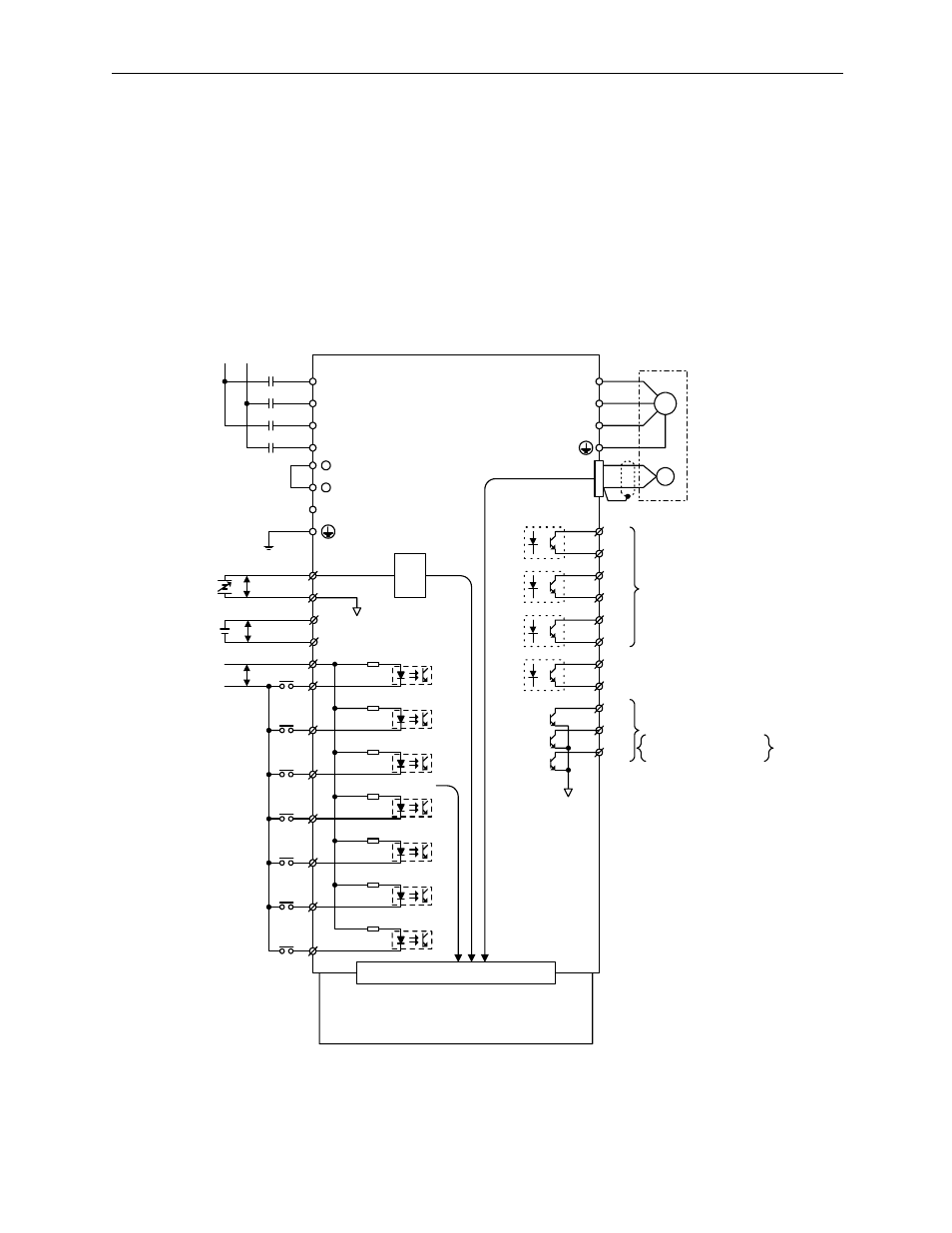
In this section, a description is given of the SGDH-E servo amplifier I/O signals as
they are used in combination with an MP940.
Schematic Diagram of I/O Signals
The typical connection of the I/O signals is shown below:
L1
L2
LC1
LC2
+
+
1
2
P
5
6
V-REF
SG
P
21
22
BAT (+)
BAT (-)
SGDH
+24V
General
Purpose
DEC
P-OT
N-OT
EXT1
EXT2
EXT3
47
40
41
42
43
44
45
46
33k
Ω
W
V
U
M
Motor
PG
CN2
~
25
26
~
27
28
~
29
30
~
31
32
37
38
39
Common Memory
A/D
SO1
SO2
SO3
Output signal mapping is
possible according to
settings Pn50E~Pn510.
ALM+
ALM-
Servo Alarm Output
ALO1
ALO2
ALO3
Alarm code Output
Max. Use Voltage DC30V
Max. Use Current DC20mA
MP940
Note: EXT3 is used for latch signal
Advertising