Yaskawa MP940 Reference Manual User Manual
Page 415
Control Mode
MotionSuite™ MP940 Machine Controller Reference Manual
11-18
The processing of these control loops inside the SVA module permits the
customer to easily direct the electronic shaft control supply, selecting phase
control mode on the CPU module side, and sending the necessary parameters
to the SVA module.
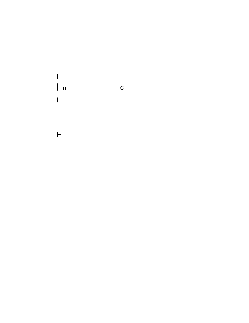
Ladder Program Example
Although the above example of the run command (DWG H04) is extremely
simplified, in reality each of the register types can be freely controlled by the
user program.
The block diagram of the MP940 SVA phase control mode follows.
RUN
OBC0010
PREPARE
MB010010
MW01010×MW01020+ML02012
VERF
GEAR1
EXTRA
÷MW01021
GEAR2
NREF
⇒ OWC015
MOD
×00001
EXTRA
⇒ ML02012
ML01012
PHBIAS
⇒ OLC016
ISO-HOSE
DEND
H0108
RUNMOD
⇒ OWC000
Phase control mode ON
Disable Phase Reference Generator
Calculation OFF
Phase control starts when the run
command to the driver (RUN) MB01010
is turned ON.
This sets the basic speed reference
(NREF).
The speed reference is stored in
MW01010. Gear ratios are stored in
MW01020 and MW01021. " 1" is stored
if gearing is not needed.
To deviate the phase, set the phase
compensation (OLC016). Store the
deiation amount (converted to pulses
from the rotation angle of the motor axis)
in ML01012.