Representative main circuit wiring – Yaskawa MP940 Reference Manual User Manual
Page 177
MotionSuite™ MP940 Machine Controller Reference Manual
Servo Amplifier Main Circuit Connection
5-35
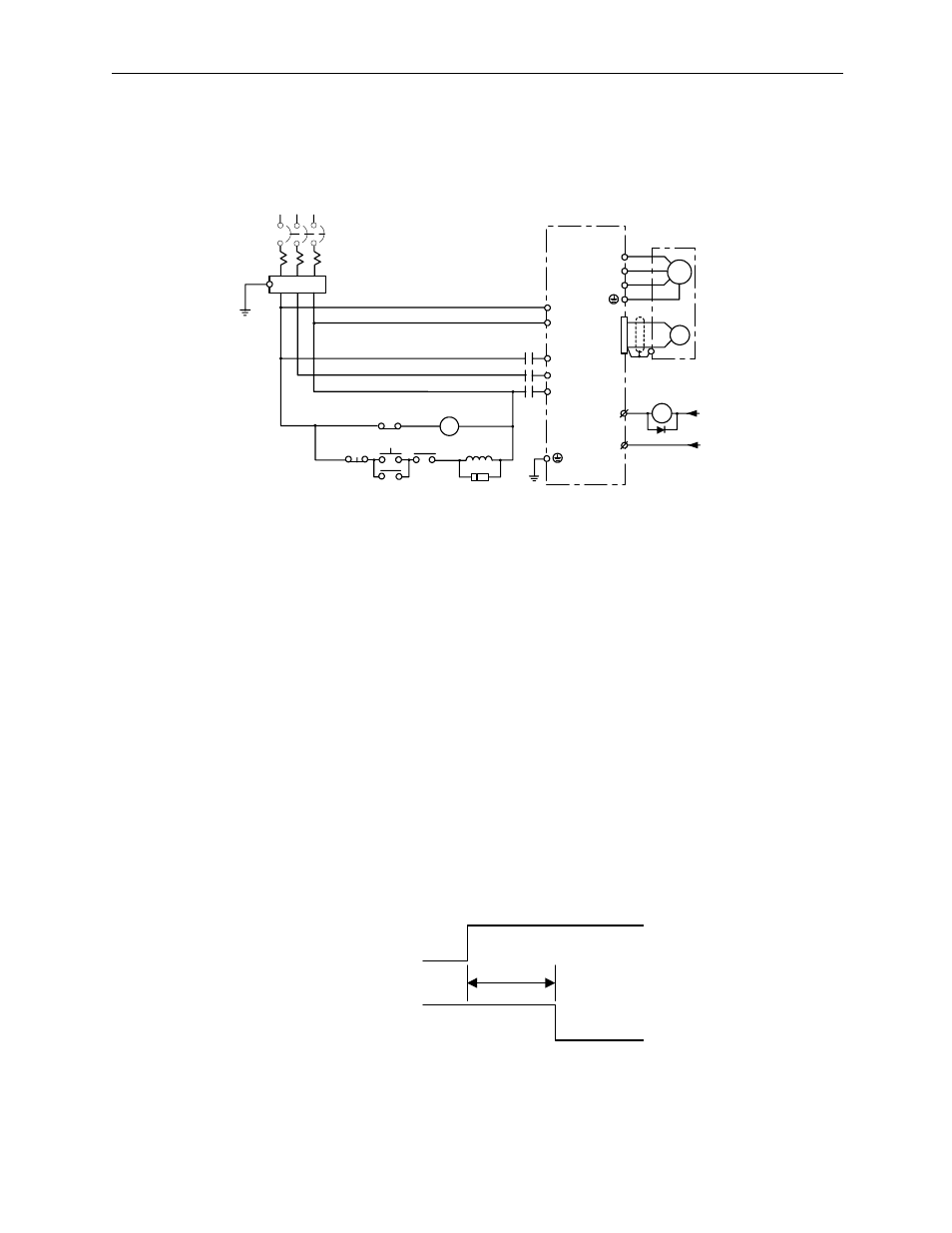
Representative Main Circuit Wiring
An example is given in the figure below of typical wiring of the main circuit.
Power Feed Sequence Setting
Keep the following points in mind when designing the power feed sequence:
• Design the power sequence so that the power goes OFF when a servo alarm
signal is output (see the above circuit).
• Push the POWER button continuously for at least 2 seconds. The servo
amplifier outputs a servo alarm signal within a maximum of two seconds of
power ON. This is necessary for initial setting of the servo amplifier.
1MCCB: Wiring Breaker (for inverters)
1Ry: Relay
FIL: Noise Filter
1PL: Display Lamp
1MC: Connector
1SUP: Surge Suppressor
1D: Flywheel Diode
M
FIL
1Ry
Main Power
ON
1Ry
Main Power
OFF
1MC
1MC
(for servo error display)
1SUP
1MC
L1
L2
L3
L1C
L2C
Servo Amplifier
SGDM-□□AD
U
V
W
A
B
C
D
PG
CN1
31
+24V
ALM
ALM
-SG
32
1D
024V
1Ry
1MCCB
R
S
T
1PL
2.0s maximum
Power
Servo Alarm
(ALM) Output
Signal