User program examples, Operation conditions – Yaskawa MP940 Reference Manual User Manual
Page 423
Control Mode
MotionSuite™ MP940 Machine Controller Reference Manual
11-26
c.) A user program must be created to connect the limit switch signal
DECLS (DI signal integrated in LIO, etc.) to the zero-point return
deceleration point limit switch LSDEC (Bit 15 of OWC001).
d.) The point at which the first zero-point pulse (C-phase pulse) after
LSEDC goes from ON to OFF is the zero-point position. The axis
decelerates to a stop after the first zero-point pulse is detected.
e.) After decelerating to stop, the axis moves at creep speed in the direc-
tion of the zero-point position for the zero-point overrun distance only,
and then stops at the zero-point position. A zero-point offset can also
be set (the position data is 100 when the zero-point position offset
OLC006 is set to 100).
Zero-point Return Mode Stop
The zero-point return operation is complete when the axis enters the
positioning completion range. The zero-point return completion signal
ZRNC (Bit F of IWC000) goes ON upon completion of the zero-point return
operation. The RUN command and zero-point return mode (ZRN) both go
OFF after it has been verified that the zero-point return completion signal
(ZRNC) is ON.
User Program Examples
Program Run Examples (zero-point return pattern)
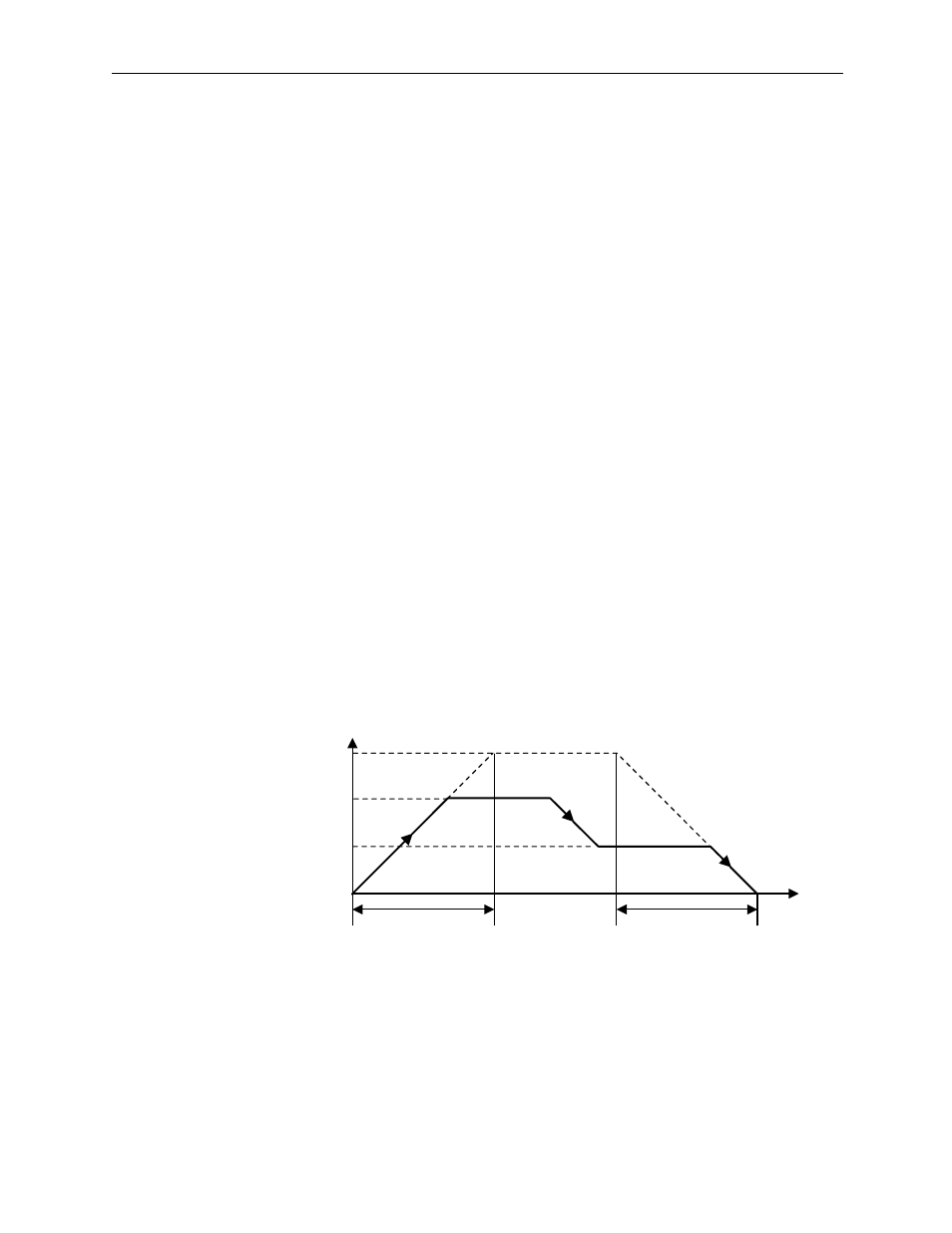
Operation Conditions
Input a limit switch signal band at least 2× the high-speed scan setting.
Speed (%)
NR
(100%)
0
NACC
NDEC
Time
(t)
Napr
Nclp
Approach Speed
Creep Speed