Sequence related parameters (continued) – Yaskawa MP940 Reference Manual User Manual
Page 288
SGDH User Parameters
MotionSuite™ MP940 Machine Controller Reference Manual
6-88
Pn507
Brake Command Output
Speed Level
rpm
0 ~ 10000
—
100
Speed
Torque
Position
Pn508
Timing for Brake
Reference during Motor
Operation (continued)
10ms
10 ~ 100
—
50
Speed
Torque
Position
User Output
Parameter Setting Terminal (CN1)
*1*2
Pn50F.20
—
1
25
26
2
27
28
3
29
30
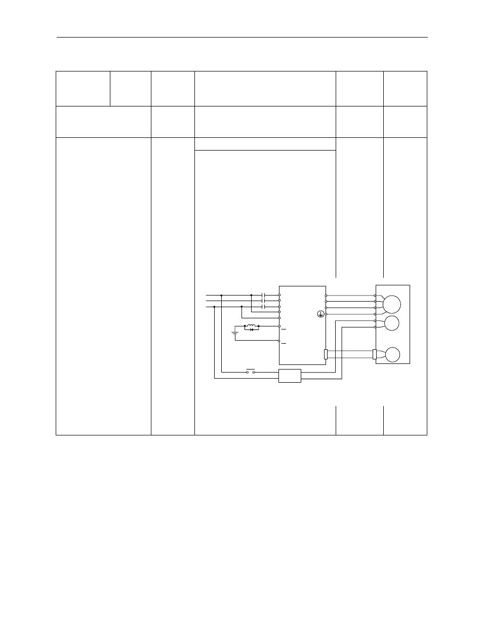
Connection Example
The brake ON/OFF circuit is configured
using the servo amplifier sequence out-
put signal /BK and the brake power. A
standard connection example is given
in the figure below.
Sequence Related Parameters (Continued)
User
Parameter
Number
Digit
Position
Name
(setting
range)
Content
Default
Setting
Control
Mode
M
BK
PG
Servo Motor w/Brake
A(1)
B(2)
C(3)
D(4)
E(5)
F(6)
U
V
W
CN2
Red
Black
Blue or
Yellow
White
AC
DC
BK-RY
BK-RY
+24V
L1
L2
L3
L1C
L2C
Brake Power
Servo
Amplifier
Power
CN1-*2
CN1-*1
Brake power is either 200V or 100V
BK-RY
: Brake Control Relay
*1,*2 : The output terminal numbers assigned in user parameter Pn50F.2.
BK+
BK-