Yaskawa MP940 Reference Manual User Manual
Page 515
MotionSuite™ MP940 Machine Controller Reference Manual
Parameters
A-28
3
Target Position
ILC002
-2
31
~2
31-1
1 = 1 pulse or 1 = 1 command unit
Update will occur even in machine lock
when 1 = 1 pulse unit
5
Incremental Target
Position
ILC004
-2
31
~2
31-1
1 = 1 pulse or 1 = 1 command unit
When pulse units 1 = 1 pulse unit
7
Machine Coordinate
Latch Position
ILC006
-2
31
~2
31-1
1 = 1 command unit
(1 = 1 pulse when pulse units)
9
Machine Coordinate
Feedback Position
ILC008
-2
31
~2
31-1
1 = 1 command unit
(1= 1 pulse when pulse units)
Note) Not updated during machine lock
11
Position Error
ILC00A
-2
31
~2
31-1
1 = 1pulse
13
Speed Reference
Output Value
IWC00C -32768~32767
1 = 0.01%
14
Speed Monitor
IWC00D -32768~32767
1 = 0.01%
15
Torque Monitor
IWC00E -32768~32767
1 = 0.01%
16
Over Range
Parameter Number
IWC00F
1~65
101~148
Motion Setting Parameter Error Number
Fixed Motion Parameter Error Number
+100
17
Number of Absolute
Encoder Turns
ILC010
0~±99999
1~1 (rotations)
19
Initial Incremental
Pulses of Absolute
Encoder
ILC012
-2
31
~2
31-1
1 = 1pulse
21
Servo Command
Type Response
IWC014
0~65535
Currently executed motion command
(for details, see OWC020)
22
Servo Module Com-
mand Status
IWC015
Bit 0: BUSY
Command execution flag
Bit 1: HOLDL
Command hold completion
Bit 2: DEN
Feed completion
Bit 3: ZSET
Zero point setting completion
Bit 4: EX_LATCH
External positioning signal latch comple-
tion
Bit 5: FAIL
Command error termination state
Bit 6: ZRNC
Zero point return completion state
Bits 7~15:
Unused
23
Number of Decimal
Places
IWC016
0~5
Fixed motion parameter
Copy of “Number of Decimal Places
Below Decimal Point”
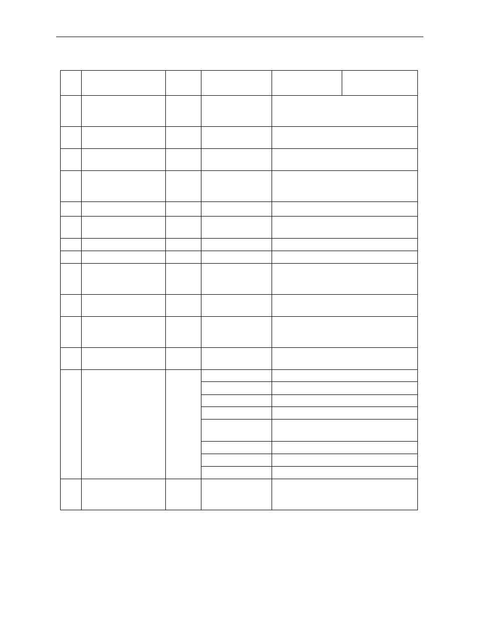
Table 9: Monitor Parameters (Continued)
No.
Name
Register
Number
Bit Name
(Setting Range)
Meaning
Note