Output signal – Yaskawa MP940 Reference Manual User Manual
Page 184
Servo Amplifier I/O Signal
MotionSuite™ MP940 Machine Controller Reference Manual
5-42
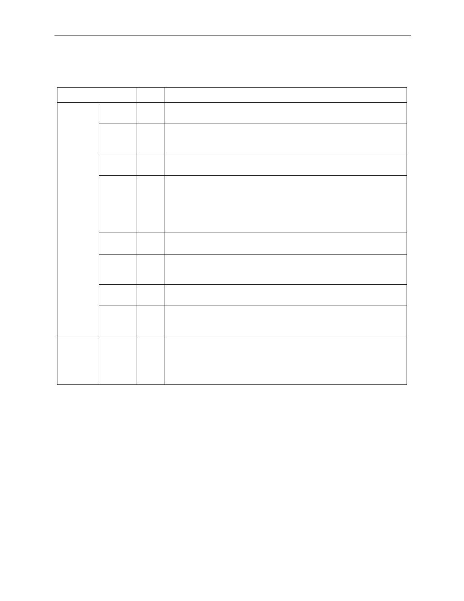
Pin numbers in parentheses are signal grounds.
The output signals /TGON, /S-RDY, and /V-CMP (/COIN) can have their function assignments changed by
the setting of user parameters. They can be changed to /CLT, /VCT, /BK, /WARN, and /NEAR signals.
Output Signal
Signal Name
Pin#
Function
Common
ALM+
ALM-
31
32
Servo Alarm: OFF due to error detection
/TGON+
/TGON-
27
28
Motor Rotation Detection: Detects whether a motor is rotating at a
speed above the set value. The detection speed can be set in the user
parameters.
/S-RDY+
/S-RDY-
29
30
Servo Ready: ON when an alarm is generated with the control/main
power ON.
33 (1)
34
35
36
19
20
Do not use.
48
49
Do not use.
ALO1
ALO2
ALO3
37
38
39 (1)
Alarm Code Output: Outputs a 3-bit alarm code.
FG
Shell
Connect the frame ground after attaching the I/O signal cable shell wire
to the connector shell.
/V-CMP+
/V-CMP-
25
26
Speed Coincidence (output in speed control mode):
Detects coincidence of the motor speed with the speed referenced in
the setting range.
Prepara-
tion
16
17
23
24
50
Empty Terminal
Note: Do not use empty terminals for relays.