Yaskawa MP940 Reference Manual User Manual
Page 149
MotionSuite™ MP940 Machine Controller Reference Manual
Handling Each Part
5-7
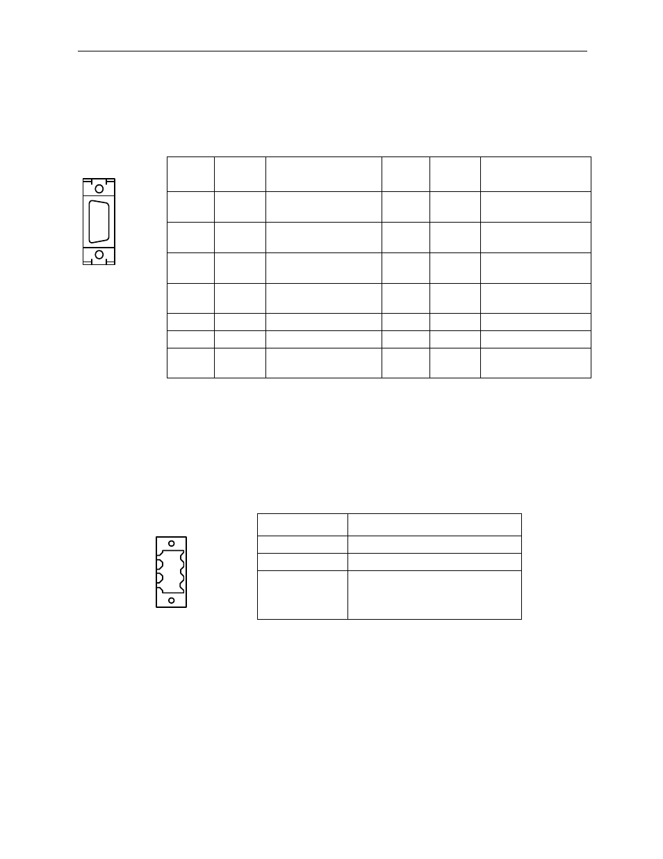
Connector pin array and signal name
The example below depicts the programming device connection to serial port
2.
Power Connector
Supplies +24VDC power to the MP940 module.
The connectors use a screw-mount terminal block BL3.,5/3F-AU
(Weidmuller, Inc.).
Number
Signal
Name
Reference
Number
Signal
Name
Reference
1
TX+
+ side of transmission
data
8
TX+
+ side of transmission
data
2
TX-
- side of transmission
data
9
TX-
- side of transmission
data
3
RX+
+ side of received data 10
RX+
+ side of received
data
4
RX-
- side of received data 11
TXR
Transmission data
terminal resistor
5
—
—
12
—
—
6
RX-
- side of received data 13
VCC
Power+5V
7
RXR
Data Reception
Terminal Resistance
14
GND
Ground
Terminal Name
Function
+24V
+24VDC
0V
0VDC
FG
Protective grounding terminal
PORT2
POWER
+24V
GND
FG