Yaskawa MP940 Reference Manual User Manual
Page 72
Functions
MotionSuite™ MP940 Machine Controller Reference Manual
3-30
Note:
After the graphical display format of the function has
been created, define the data types of the function
inputs, outputs, and address inputs.
There are three types of definable data types: bit, inte-
ger, and double-length integer.
Upon defining the data types, these are automatically
assigned according to the system where input = X reg-
ister, output = Y register, address input = A register.
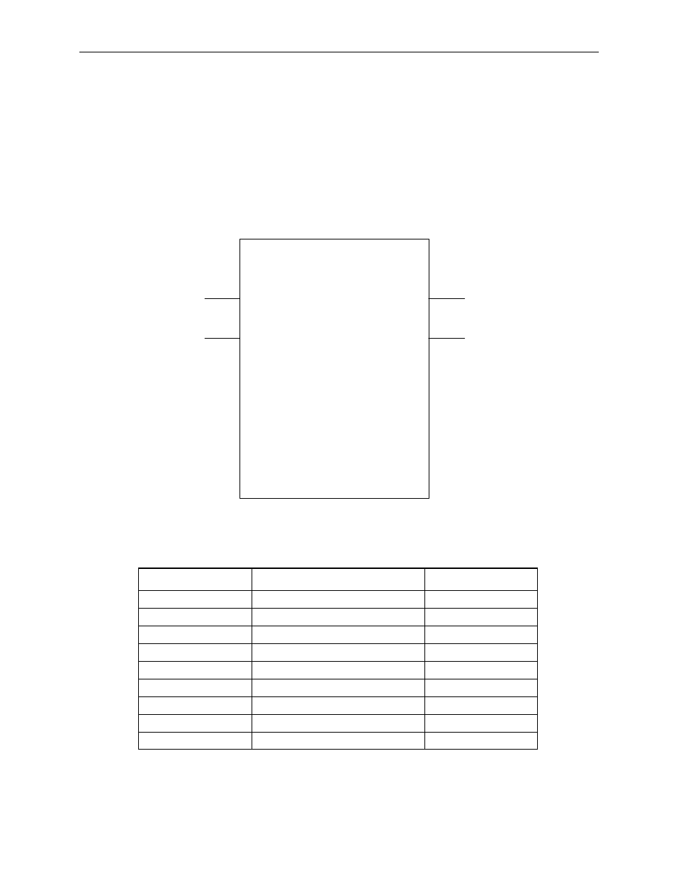
2. An example of the function input definitions is given below:
3. The I/O signal addresses are automatically assigned from the signals on
the graphical expression. Each of the I/O address assignments in the
example above are as follows:
•
XW00000 and YW00000 of the X and Y registers are used as bit type data.
Name
Data Type
I/O Register
IN_01 (BIT1)
Bit type
XB000000
IN_02 (BIT2)
Bit type
XB000001
IN_03 (FLT1)
Real number type
XF00001
IN_04 (INT1)
Integer type
XW00003
IN_05 (ADR)
Address input type
AW00000
OUT_01 (BIT3)
Bit type
YB000000
OUT_02 (BIT4)
Bit type
YB000001
OUT_03 (LNG1)
Double-length integer type
YL00001
OUT_04 (INT2)
Integer type
YW00003
TEST
IN_01
IN_02
IN-03
IN-04
IN_05
OUT_01
OUT_02
OUT_03
OUT_04
BIT1
BIT2
FLT1
INT1
INT2
LNG1
BIT4
BIT3
===>
===>
===>
===>
Bit-type
Numerical Input
Bit-type
Numerical Input
Bit-type
Numerical Output
Bit-type
Numerical Output
Real Number
Numerical Input
Integer
Numerical Input
Double-length
Integer Numerical
Output
Integer
Numerical Output
ADR