Schematic diagram of the led block – Yaskawa MP940 Reference Manual User Manual
Page 153
MotionSuite™ MP940 Machine Controller Reference Manual
Handling Each Part
5-11
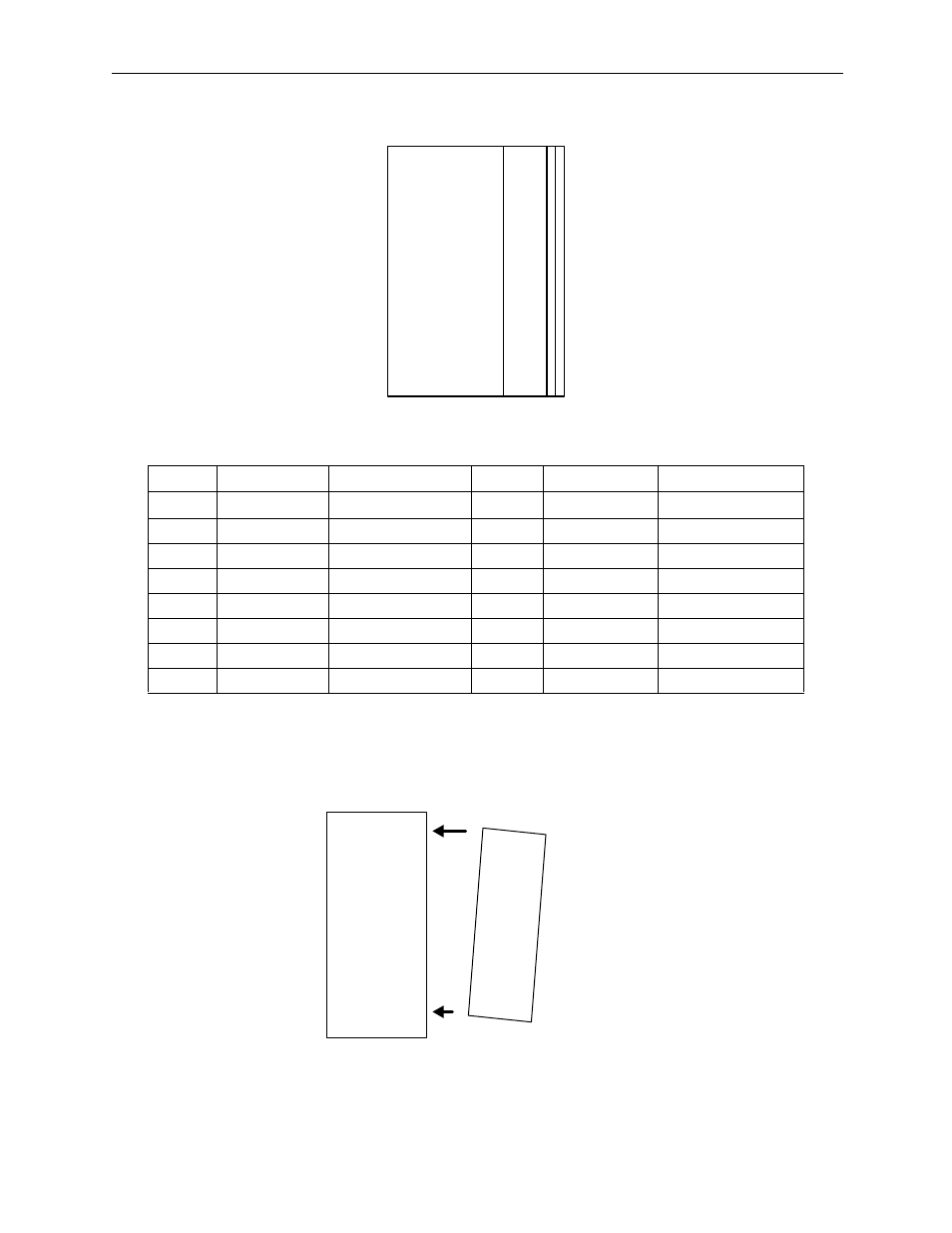
Schematic diagram of the LED block
Other numbers and symbols are unused.
Note: The MP940 is mounted to the side of an SGDH servo amplifier. Securely mount the MP940 in the
correct direction with regard to the SGDH amplifier.
Turn the power ON in the SGDH within 10 seconds of turning the power ON in the MP940. If the
SGDH amplifier power is not tuned ON within ten seconds, the MP940 will not operate synchro-
nously with the SGDH, and stand-alone operation results.
Number
Signal Name
Meaning when Lit
Number
Signal Name
Meaning when Lit
1
DI 0
DI 0 Input
9
DO 0
DO 0 Output
2
DI 1
DI 1 Input
10
DO 1
DO 1 Output
3
DI 2
DI 2 Input
12
DO 2
DO 2 Output
4
DI3
DI 3 Input
13
DO 3
DO 3 Output
5
DI 4
DI 4 Input
13
DO 4
DO 4 Output
6
DI 5
DI 5 Input
14
DO 5
DO 5 Output
8
DI 6
DI 6 Input
15
DO 6
DO 6 Output
9
DI 7
DI 7 Input
16
DO 7
DO 7 Output
R ACTIVE F
1 9 17 25
2 10 18 26
3 11 19 27
4 12 20 28
5 13 21 29
6 14 22 30
7 15 23 31
8 16 24 32
SGDH
MP940