Encoder wiring, Servo amplifier – Yaskawa MP940 Reference Manual User Manual
Page 188
Advertising
Encoder Wiring
MotionSuite™ MP940 Machine Controller Reference Manual
5-46
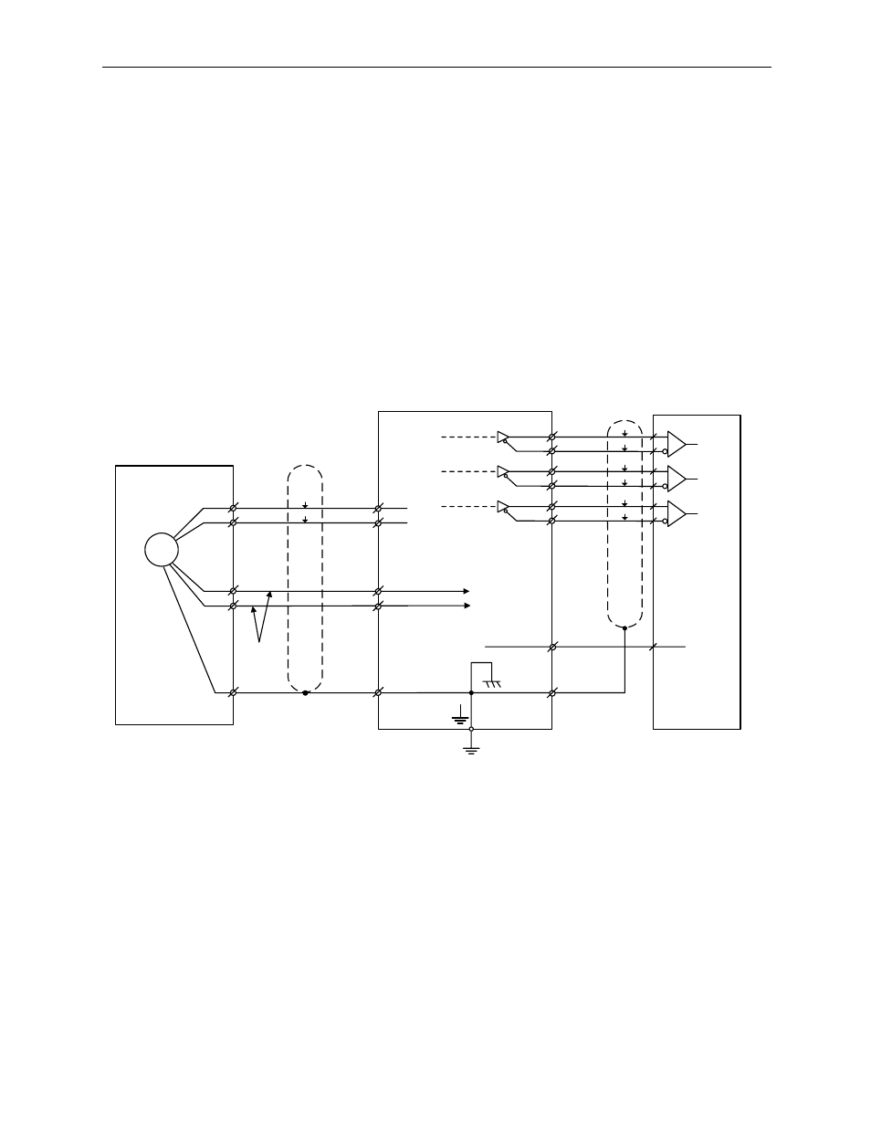
Encoder Wiring
The wiring of the servo amplifier to the encoder is described below.
Connection with the Encoder (CN2) and Output Signal
Processing from the Servo Amplifier (CN1)
The examples below illustrate both an incremental encoder and an absolute
encoder.
Incremental Encoder
Blue
Lt. Blue
Red
Black
0.33mm
2
Shield Line
Connector
Shell
ov
SG
1-1
ov
(Customer Side)
Output Line Driver:
T/ISN75ALS194-
compatible
Applied Line
Driver:
T/I SN75175-
compatible
PAO
*PAO
PBO
*PBO
PCO
*PCO
∗
Connector
Shell
Incremental Encoder
PG5V
PG0V
2-1
2-2
2-5
2-6
CN2
Servo Amplifier
A-phase
B-phase
C-phase
C(5)
1-33
1-34
1-35
1-36
1-19
1-20
P
P
P
P
PG
D(6)
H(1)
G(2)
(Shell)
CN1
J
∗
Advertising
See also other documents in the category Yaskawa Equipment:
- Tag Generator (30 pages)
- MP3300iec (82 pages)
- 1000 Hz High Frequency (18 pages)
- 1000 Series (7 pages)
- PS-A10LB (39 pages)
- iQpump Micro User Manual (300 pages)
- 1000 Series Drive Option - Digital Input (30 pages)
- 1000 Series Drive Option - CANopen (39 pages)
- 1000 Series Drive Option - Analog Monitor (27 pages)
- 1000 Series Drive Option - CANopen Technical Manual (37 pages)
- 1000 Series Drive Option - CC-Link (38 pages)
- 1000 Series Drive Option - CC-Link Technical Manual (36 pages)
- 1000 Series Drive Option - DeviceNet (37 pages)
- 1000 Series Drive Option - DeviceNet Technical Manual (81 pages)
- 1000 Series Drive Option - MECHATROLINK-II (32 pages)
- 1000 Series Drive Option - Digital Output (31 pages)
- 1000 Series Drive Option - MECHATROLINK-II Technical Manual (41 pages)
- 1000 Series Drive Option - Profibus-DP (35 pages)
- AC Drive 1000-Series Option PG-RT3 Motor (36 pages)
- Z1000U HVAC MATRIX Drive Quick Start (378 pages)
- 1000 Series Operator Mounting Kit NEMA Type 4X (20 pages)
- 1000 Series Drive Option - Profibus-DP Technical Manual (44 pages)
- CopyUnitManager (38 pages)
- 1000 Series Option - JVOP-182 Remote LED (58 pages)
- 1000 Series Option - PG-X3 Line Driver (31 pages)
- SI-EN3 Technical Manual (68 pages)
- JVOP-181 (22 pages)
- JVOP-181 USB Copy Unit (2 pages)
- SI-EN3 (54 pages)
- SI-ET3 (49 pages)
- MECHATROLINK-III (35 pages)
- EtherNet/IP (50 pages)
- SI-EM3 (51 pages)
- 1000-Series Option PG-E3 Motor Encoder Feedback (33 pages)
- 1000-Series Option SI-EP3 PROFINET (56 pages)
- PROFINET (62 pages)
- AC Drive 1000-Series Option PG-RT3 Motor (45 pages)
- SI-EP3 PROFINET Technical Manual (53 pages)
- A1000 Drive Option - BACnet MS/TP (48 pages)
- 120 Series I/O Modules (308 pages)
- A1000 12-Pulse (92 pages)
- A1000 Drive Software Technical Manual (16 pages)
- A1000 Quick Start (2 pages)
- JUNMA Series AC SERVOMOTOR (1 page)
- A1000 Option DI-101 120 Vac Digital Input Option (24 pages)