Yaskawa MP940 Reference Manual User Manual
Page 498
MotionSuite™ MP940 Machine Controller Reference Manual
Switch List
A-11
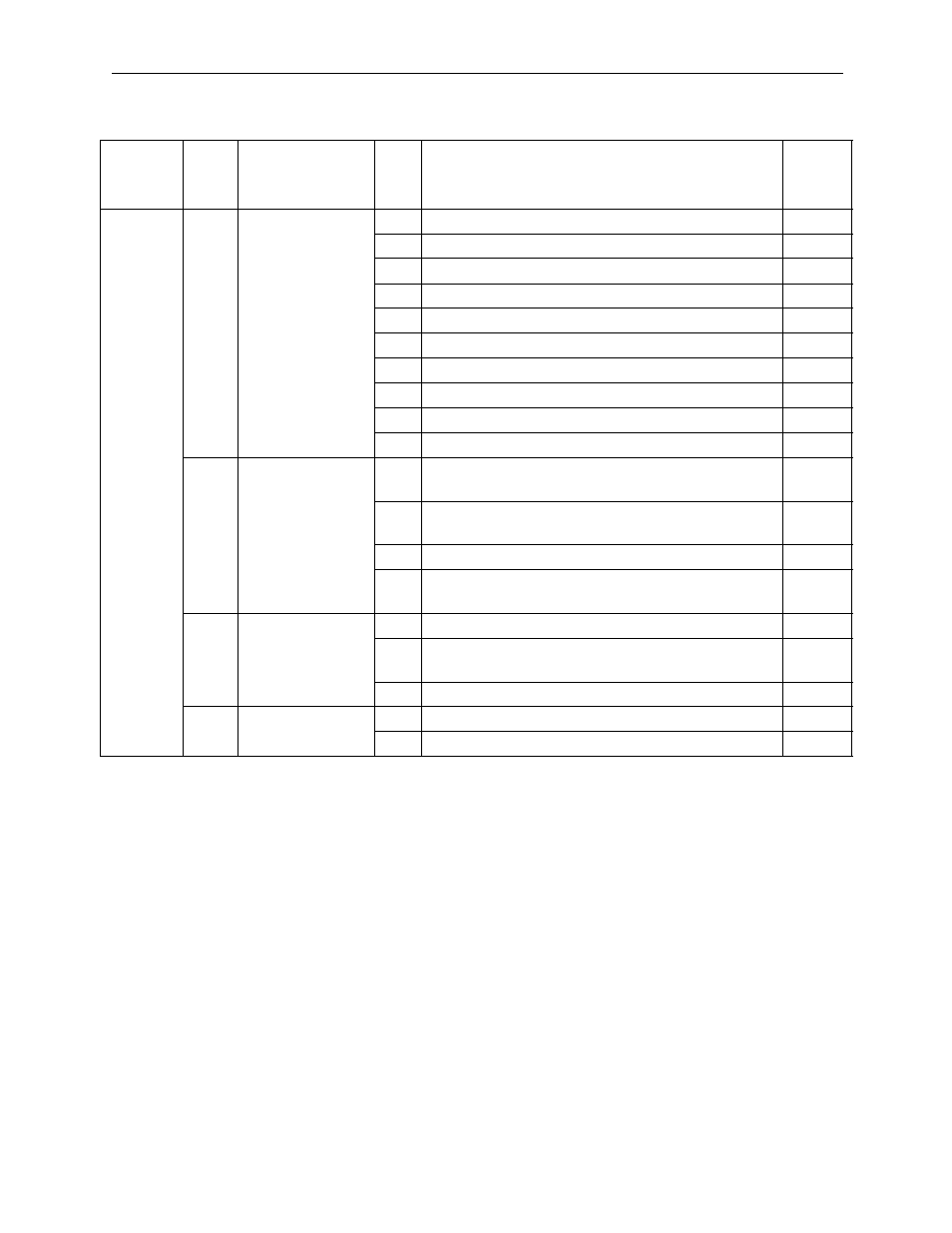
Pn200
Position
Control
0
Command Pulse
Form
0
Sign + pulse, positive logic
0
1
CWCCW, positive logic
—
2
A-phase + B-phase (no multiplier), positive logic
—
3
A-phase + B-phase (2× multiplier), positive logic
—
4
A-phase + B-phase (quadrature), positive logic
—
5
Sign + pulse, negative logic
—
6
CWCCW, negative logic
—
7
A-phase + B-phase (no multiplier), negative logic
—
8
A-phase + B-phase (2× multiplier), negative logic
—
9
A-phase + B-phase (quadrature), negative logic
—
1
CLEAR Signal
Form
0
Clear the deviation counter with the signal “H”
level.
0
1
Clear the deviation counter with the upward transi-
tion of the signal.
—
2
Clear the deviation counter with the signal “L” level. —
3
Clear the deviation counter with the downward
transition of the signal.
—
2
CLEAR Operation 0
Clear the deviation counter during base block.
0
1
Does not clear the deviation counter.
(cleared only by the CLR signal)
—
2
Clear the deviation counter at alarm occurrence.
—
3
Filter Selection
0
Command Input Filter for Line Driver Signal
0
1
Command Input Filter for Open Collector Signal
—
Table 2: Switches (Continued)
User
Parameter
Number
De
c
im
a
l
Pl
ac
e
Name
S
e
tti
ng
Content
Factory
Setting