I/o connector pin array and i/o circuit – Yaskawa MP940 Reference Manual User Manual
Page 163
MotionSuite™ MP940 Machine Controller Reference Manual
Connection Method
5-21
I/O Connector Pin Array and I/O Circuit
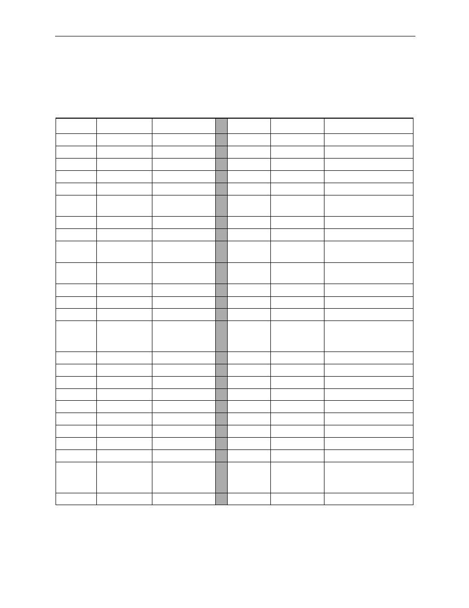
The names and content of each of the I/O connector terminals is shown in the
table below.
Number
Signal Name
Reference
Number
Signal Name
Reference
1
AO
Analog Output
26
AO_GND
Analog Output Ground
2
—
—
27
—
—
3
—
—
28
—
—
4
PA+
A_ Pulse +
29
PB+
B_Pulse +
5
PA-
A_ Pulse -
30
PB-
B_Pulse -
6
GND
Pulse Input
Ground
31
GND
Pulse Input Ground
7
—
—
32
—
—
8
—
—
33
—
—
9
PILC 5V
PI Latch Input
Common (5V)
34
PILC 12V
PI Latch Input
Common (12V)
10
PILC 24V
PI Latch Input
Common (24V)
35
PIL
PI Latch Input
11
—
—
36
—
—
12
—
—
37
—
—
13
DC 24V
DI Power (input)
38
DC 24V
DI Power (input)
14
DI_00
DI_00
Input
(DI interrupt)
39
DI_01
DI_01 Input
15
DI_02
DI_02 Input
40
DI_03
DI_03 Input
16
DI_04
DI_04 Input
41
DI_05
DI_05 Input
17
DI_06
DI_06 Input
42
DI_07
DI_07 Input
18
—
—
43
—
—
19
—
—
44
—
—
20
DC 24V
DO Power (input)
45
DC 24V
DO Power (input)
21
DO_00
DO_00 Output
46
DO_01
DO_01 Output
22
DO_02
DO_02 Output
47
DO_03
DO_03 Output
23
DO_04
DO_04 Output
48
DO_05
DO_05 Output
24
DO_06
DO_06 Output
49
DO_07
DO_07
Output (Counter
coincidence output)
25
DO_GND
DO Ground(0V)
50
DO_GND
DO Ground(0V)