Monitor parameters, Table 9: monitor parameters – Yaskawa MP940 Reference Manual User Manual
Page 514
MotionSuite™ MP940 Machine Controller Reference Manual
Parameters
A-27
Monitor Parameters
The monitor parameters are sent to the controller as a group at the start of
each high-speed scan. Use them for application control, user program
debugging, etc.
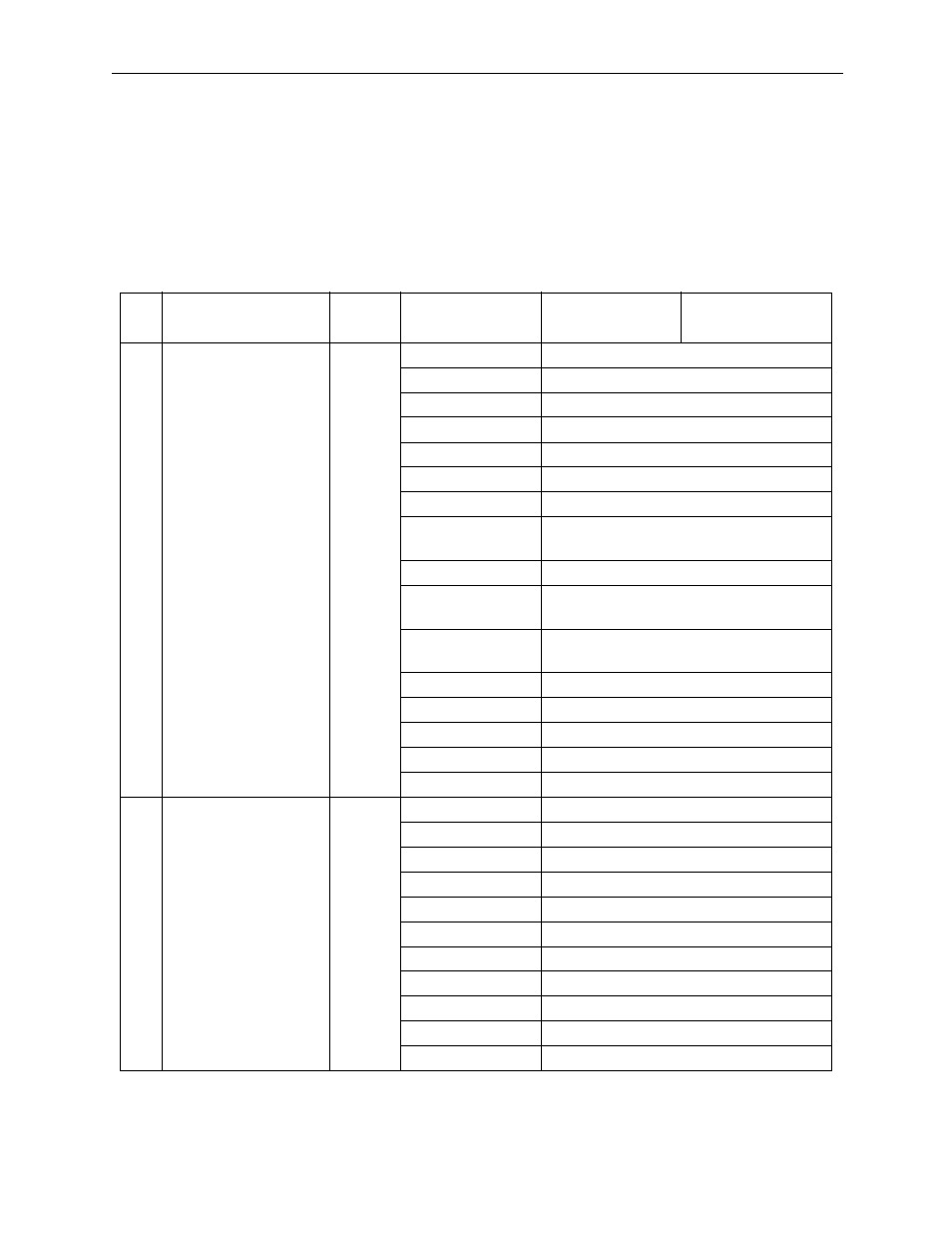
Table 9: Monitor Parameters
No.
Name
Register
Number
Bit Name
(Setting Range)
Meaning
Note
1
Drive Status
IWC000
Bit 0: EOVER
Deviation Error
Bit 1: PRMERR
Motion setting parameter setting error
Bit 2: FPRMERR
Motion setting parameter setting error
Bit 3: Unused
—
Bit 4: Unused
—
Bit 5: Unused
—
Bit 6: Unused
—
Bit 7: SVCRDY
Motion controller run preparation
complete
Bit 8: SVCRUN
Motion controller run
Bit 9: DIRINV
Rotation direction messaging during
absolute encoder use
Bit 10: ABCRDC
Absolute position readout completion
signal
Bit 11: DIINT
DI Latch completion signal
Bit 12: FBPO
Feedback pulse 0
Bit 13: POSCOMP Positioning completion signal
Bit 14: Unused
—
Bit 15: ZRNC
Zero-point return completion
2
Network Servo
Status
IWC001
Bit 0: ALM
Servo alarm
Bit 1: WARN
Warning
Bit 2: V-CMP
Speed coincidence
Bit 3: TGON
Motor rotation detection
Bit 4: S-RDY
Servo Ready
Bit 5: CLT
Torque limit detection
Bit 6: VLT
Speed limit detection
Bit 7: BK
Brake interlock
Bit 8: SVON
Servo ON completion
Bit 9: PON
Main circuit completion
Bit10~Bit15
Unused