User parameters (continued) – Yaskawa MP940 Reference Manual User Manual
Page 260
SGDH User Parameters
MotionSuite™ MP940 Machine Controller Reference Manual
6-60
Pn001
Function Selection
Application
Switch 1
(continued)
3
Warning
Code
Output
Selection
(contin-
ued)
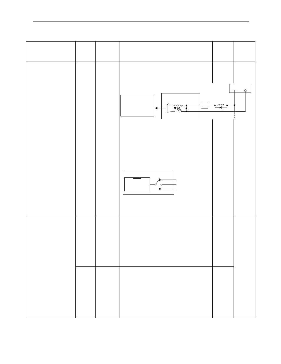
(Note)
*
1
, *2 are the output terminals assigned in user
parameter Pn503F.3.
Related Parameters
Pn50F.3: Select which CN1 terminal outputs
the /WARN signal.
0
Speed
Torque
Position
Pn002
Function Selection
Application
Switch 2
0
Speed
Control
Option
(0, 1, 2)
In Speed Control: When /P-CON(/C-SEL) is
ON, The command to the torque reference
input becomes the torque reference limit.
Always be sure to set 1 when using with the
MP940.
0: Do not set.
1: Speed control with torque limit according
to the analog voltage reference.
2: Do not set.
1
Speed
Torque
Position
1
Torque
Control
Option
(0, 1 )
In Torque Control: When /P-CON(/C-SEL) is
OFF, the command to the speed reference
input becomes the speed limit.
Always be sure to set 1 when using with the
MP940.
0: Do not set.
1: Torque control with speed limit according
to the analog voltage reference.
2: Do not set.
1
User Parameters (Continued)
User Parameter
Number
Digit
Position
Name
(Setting
Range)
Contents
Default
Setting
Control
Mode
Photocoupler Output
Max. Use Voltage:
DC30V
Ma. Output Current: :
DC50mA
Per Output
Servo Amplifier
CN1-*1
CN1-*2
WARN
+
WARN
-
24V Power
+24V
0V
Output
Terminals
CN1-25,26 (SO1)
CN1-27,28 (SO2)
CN1-29,30 (SO3)
WARN
Warning
Output
2
3
1
Pn50F.3