Yaskawa MP940 Reference Manual User Manual
Page 367
Troubleshooting
MotionSuite™ MP940 Machine Controller Reference Manual
10-14
A.71
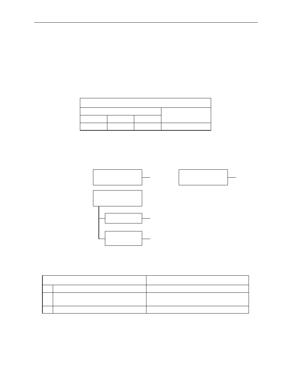
A.71 is the overload alarm display. The alarm display and status when alarm
occurs are the same in A.71 as for A.72.
A.72
A.72 is the underload alarm display. The alarm output appears below.
Note: The indicates the output transistor is ON; the X indicates the output transistor is OFF
(alarm state).
Status when Alarm Occurred
Alarm Output
Alarm Code Output
ALM Output
ALO1
ALO2
ALO3
x
Cause
Remedy
A
Servo wiring is incorrect or disconnected.
Check wiring and connections at servo motor.
B
Load greatly exceeds rated torque.
Reduce load torque and inertia. Otherwise
replace with larger capacity servo motor.
C
Circuit board (1PWB) defective.
Replace servo amplifier.
Alarm occurs at power ON
C
A
Alarm occurs at servo ON
(/S-ON) signal ON
B
Alarm occurs when speed
reference input is added
Motor does not turn
Alarm occurs
during normal
operation
B