Yaskawa MP940 Reference Manual User Manual
Page 162
Advertising
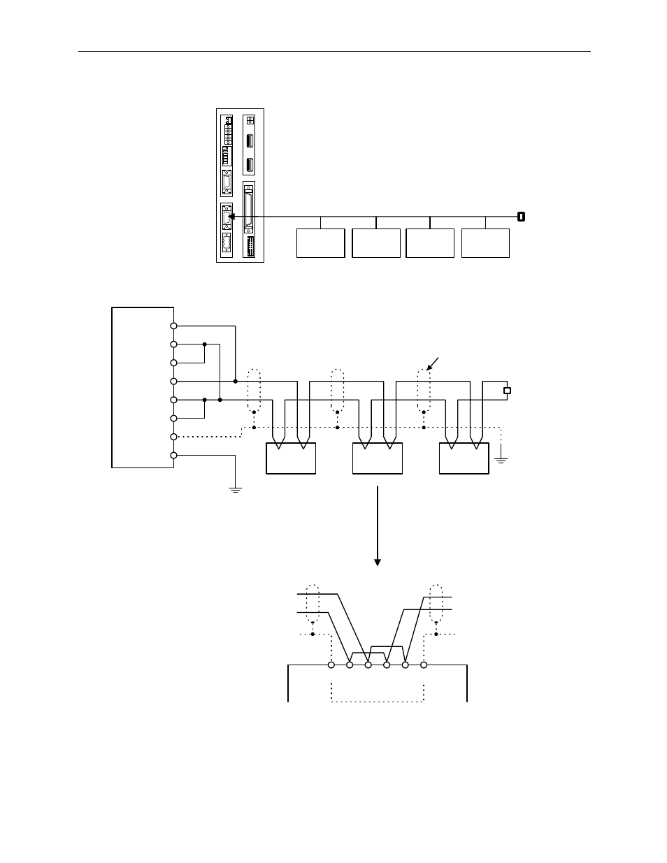
Connection Method
MotionSuite™ MP940 Machine Controller Reference Manual
5-20
RS-485 Wiring
Enable the terminal resistor in the MP940 Port2 by connecting pin 2 to pin
11, and pin 4 to pin 7.
BAT
RDY
RUN
ALM
BAT
PRT1
6
5
4
3
2
1
NO
→
PRT2
RUN
INIT
TEST
FLASH
PP
COPY
PORT1
PORT2
POWER
+24V
GND
FG
LED
I/O
TX
R
X
1
2
M
E
C
H
A
T
R
O
L
I
N
K
MP940
端末装置
(PLCなど)
端末装置
(PLCなど)
端末装置
(PLCなど)
端末装置
(PLCなど)
:120Ω終端抵抗
RS-485
MP940
120
Ω terminal resistor
Terminal
Devices
(e.g. PLC)
Terminal
Devices
(e.g. PLC)
Terminal
Devices
(e.g. PLC)
Terminal
Devices
(e.g. PLC)
120
Ω
Terminal
Resistor
TX/RX
TX/RX
TX/RX
1
TX(+)
2
TX(-)
11
TXR
3
RX(+)
4
RX(-)
7
RXR
3
SH
14
SH
FG
MP940 PORT2
FG
①
②
シールド
例えば,中間に217IFが
接続された場合は以下の
ようになります。
120Ω
終端抵抗
SH TX
(-)
TX
(+)
RX
(-)
RX
(+)
SH
3
6
7
1
2
8
①
②
Shield
Terminal
Resistor
The following results when an
MP940 is connected as a node.
SHIELD
GND
2
1
4
3
Advertising