Formation of dormant links, Selection of active link, Mesh network topologies – H3C Technologies H3C WX3000E Series Wireless Switches User Manual
Page 457: Point to point connection, Point to multi-point connection
436
•
Link hold time—An active link remains up within the link hold time, even if the link switch margin is
reached. This mechanism is used to avoid frequent link switch.
•
Link saturation RSSI—This is the upper limit of RSSI on the active link. If the value is reached, link
switch occurs.
Formation of dormant links
A train MP performs active scanning to find neighboring rail MPs by sending probe requests at a very
high rate. Based on probe responses received, the train MP forms a neighbor table.
After that, the train MP creates dormant links with rail MPs that have an RSSI value greater than the link
formation RSSI.
Selection of active link
A train MP selects the active link from dormant links based on the following rules:
1.
If no dormant link is available, the active link cannot be formed.
2.
Active link switch will not happen within the link hold time, except the following two conditions:
Condition 1—The active link RSSI exceeds the link saturation RSSI.
Condition 2—The active link RSSI is below the link hold RSSI.
3.
When the link hold timer expires, if no dormant link has RSSI greater than the active link RSSI by
the link switch margin, link switch does not happen.
4.
In normal scenarios, active link switch does happen when all of these following conditions are met:
The link hold timer expires.
The dormant link's RSSI is higher than the current active link's RSSI by the link switch margin.
The dormant link RSSI is not greater than the link saturation RSSI.
5.
Once the RSSI of the active and dormant links has gone below the link hold RSSI, links should be
broken. However, to ensure service availability in worse cases, if the active link RSSI has gone
below the link hold RSSI and no dormant links exist, the active link is not broken.
Mesh network topologies
The mesh feature supports the following three topologies. Mesh is implemented through configuration of
a peer MAC address for each AP. For more information, see "
Configuring a peer MAC address
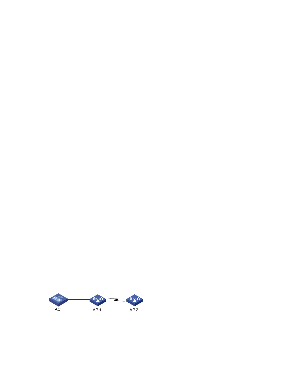
Point to point connection
In this topology, by configuring the peer MAC address for an AP, you can determine the mesh link to be
formed.
Figure 460 Mesh point to point topology
Point to multi-point connection
In this topology, a centralized bridging device forms wireless links with multiple MPs to bridge data
among multiple LAN segments. As shown below, data transferred between different LAN segments goes
via AP 1.